e
Light Blue
White
White
Centrifugal Switch (Motor)
Gas Valve, Gas Dryer
Pluggable Drive Motor Switch
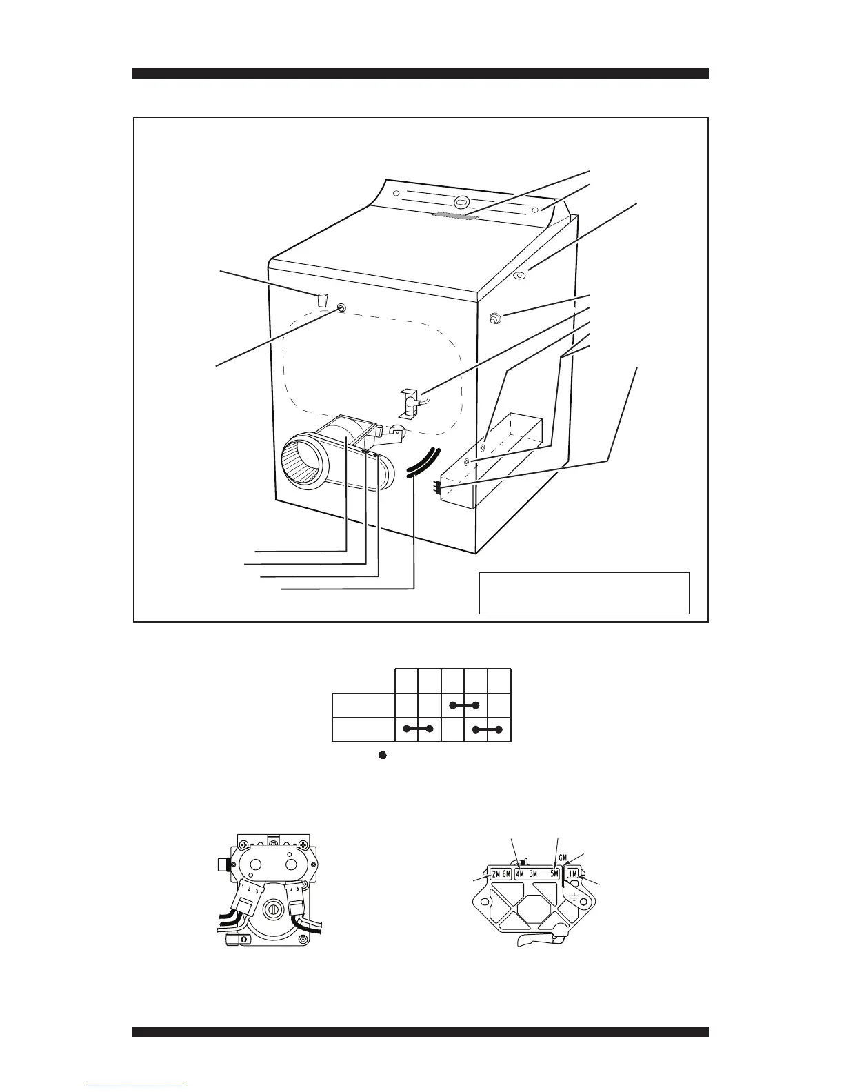
COMPONENT LOCATIONS
• ACU (beneath console)
• User Interface (UI)
• Inlet Thermistor (Gas)
• Water Nozzle
• Water Valve
• Thermal Cut-off
• Inlet Thermistor (Electric)
• High Limit Thermostat
• Heater Assembly
Drum Light
Assembly
Door Switch
(Location may vary
between models)
• Motor Assembly
• Thermal Fuse
• Outlet Thermistor
• Moisture Sensor Strips
Figure 16 - Component locations.
NOTE: Refer to Figure 10b, page 17,
for gas dryer component locations.