13
FOR SERVICE TECHNICIAN ONLY - DO NOT REMOVE OR DESTROY
Be sure to perform the Diagnostic Tests before replacing the
system components.
Pump Motor Continuity Test
Pins
Results
1 to 2 Normal = approx. 12.3 Ω
Abnormal = Infinity
Motor Continuity Test
1. Unplug washer or disconnect power.
2. Disconnect the wire harness from the motor and measure the
resistance of the motor. Use the following table:
Pins
Results
1 to 2 Normal = approx. 6.45 Ω
2 to 3 Abnormal = Infinity
1 to 3
Water Temperature Sensor
1. Unplug washer or disconnect power.
2. Disconnect the wire harness from the water temperature sensor
and measure the resistance of the sensor. Use the following
table. An abnormal condition is an open circuit.
Temperature
Results
32°F (0°C) 35.9 kΩ
86°F (30°C) 9.7 kΩ
104°F (40°C) 6.6 kΩ
122°F (50°C) 4.6 kΩ
140°F (60°C) 3.2 kΩ
158°F (71°C) 2.3 kΩ
203°F (96°C) 1 kΩ
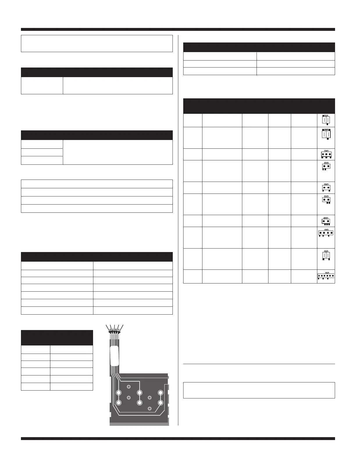
Keypad Continuity Test
Check Between
Button Contacts
A 4 and 5
B 2 and 5
C 3 and 5
D 4 and 1
E 2 and 1
F 3 and 1
Manually Unlocking the Door Lock System
1. Unplug washer or disconnect power.
2. Remove the lower kick panel.
3. Reach up along the inside of the front and locate the bottom
of the door switch/lock mechanism.
4. Located on the bottom of the door switch/lock mechanism
is a tear-drop shaped tab.
5. Gently pull the tab down about 1/4" (6 mm) or until a click is
heard.
6. The door may be opened.
ELECTRONIC ASSEMBLIES -
REMOVAL OR REPLACEMENT
IMPORTANT: Electrostatic (static electricity) discharge may cause
damage to electronic control assemblies. See page 1 for details.
NOTE: Be sure to perform the Diagnostic Tests before replacing the
control board.
**The number 1 pin has been marked on the bottom part of the connector.
**An infinity measurement occurs when the multimeter does not detect an ohm reading.
CCU Wire Harness Connector Table
Unplug washer or disconnect power before taking ohm measurements.
Primary 30-35 ohms
Blue to blue 1 ohm
White to white 2 ohms
Yellow to blue 0.5 ohms
Transformer Connector
F
C
E
B
D
A
WSH138255 REV A
WSH135640001
DC 03/13/09
18:34:00 [WSH 4876]
5 4 3 2 1
Water Temperature Table
Hot 113°F (45°C)
Warm 91.4°F (33°C)
Cold Tap
Temp Setting Targeted Temp
(Ω) Ohm Abnormal Pin Wire
Terminal Component Value Value Connectors* Coding
RP2 Wax Motor 1.2 kΩ Infinity** 1, 2
at 25°C
DLS2 Door Locked Switch Continuity: 1, 2
Locked/Unlocked door locked.
No Continuity:
door unlocked.
DL3 Door Lock Coil 165 Ω Infinity**
1, 2 door lock
Locked or Unlocked
2, 3 door unlock
SET2 Temperature Varies with Infinity** 1, 2
Sensor temperature
changes.
See above.
DP2 Drain Pump 13 Ω Infinity** 1, 2
DCS3 Door Switch Continuity 1, 2
at door close.
No continuity
at door open.
VSF2 Hot Inlet Valve #1 812 Ω Infinity** 1, 3 (hot
valve #1)
VCH7 Cold Inlet Valve #3 812 Ω, Infinity** 1, 3 (cold
Cold Inlet Valve #2 either coil
(or more than
valve #3)
10% lower
5, 7 (cold
or higher) valve #2)
IF2 RFI/UIC Transformer 30 Ω
Infinity**
1, 2
(or more than
10% lower
or higher)
PS8 Pressure Sensor
Infinity**
4, 7, and 8