For Service Technician Use Only
DIAGNOSTICS
1-28
n
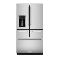
French-Door Boom Mount Refrigerator
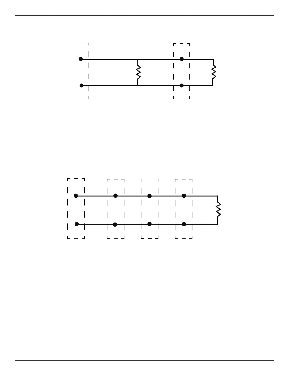
Remove dispenser UI and locate Dispenser heater wiring connector (2 wire connector, 1 red, 1 white).
• Disconnect the 2 Pin Connector (Figure 8).
• Take resistance reading on side leading to visible heater
(Dispenser Heater). Reading should be ≈108 ohms.
• Take resistance reading on other side of connector (IM Duct
Heater--Door). Reading should be ≈108 ohms.
• Ensure LED display shows “on”
• If LED display does not show “on”, replace Dispenser UI.
If all checks are OK and problems persist:
• Use up or down arrow to change acvaon mode to “01”
• Press the “Icemaker2” key to conrm selecon.
The Mullion heater resistance can be checked at mulple points. The easiest is under the le hinge cover, or at the heater itself.
Check the resistance of the Mullion Heater. Reading
should be ≈17 ohms.
• Ensure LED display shows “on”
• If LED display does not show “on”, replace Eyebrow UI.
If all checks are OK and problems persist:
• Use up or down arrow to change acvaon mode to “01”
• Press the “Icemaker2” key to conrm selecon.
J8-2
Dispenser UI
Pin 2
WH
+12.7 VDC
WH
Pin 1
J8-1
Neutral
RD RD
IM Duct
Heater
Dispenser
Heater
2 Pin Connector
behind Dispenser UI
at Mullion Heater
2 Pin Connector
J2-3
Eyebrow UI
Pin 2
YL
+ 14 VDC
WH
Pin 1
J2-4
Neutral
BK/YL RD
Mullion
Heater
Pin 1 in 1P
Pin 2Pin 2
YL YL
BK/YL BK/YL
2 Pin Connector
Left Hinge Cover behind Dispeser UI
4 Pin Connector