For Service Technician Use Only
DIAGNOSTICS
1-30
n
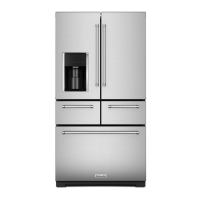
French-Door Boom Mount Refrigerator
or
Check the results of the test:
• If any errors are reported (“E1”, “E2”, “E3”, or “E4”), replace
the Ice Maker
• If the Ice maker indicates the Ice Bin is full (“IB”) verify the Ice
Bin is full. If it is not, replace the Ice Maker.
Verify the Ice Bucket Switch funcons properly:
• Verify display reads “00” with no Ice Bucket installed.
• Verify display reads “01” with the Ice Bucket installed.
If the switch does not indicate properly, replace the Ice Bin
Switch.
Verify the Ice Dispensing components are funconing properly.
• Press Ice Paddle. Ensure Display reads “1”
If display does not read “1” ensure all wiring connectors are
ght.
If all connectors are ght, replace the Ice Paddle, or switch, as
appropriate.
• Press “Cubed Ice” on the Dispenser UI. Ensure Display
momentarily reads “1”
If display does not read”1” while buon is pressed, Ensure all
wiring connectors are ght.
If all connectors are ght, Replace the Dispenser UI.
• Press “Crushed Ice” on the Dispenser UI. Ensure display
momentarily reads “1”
If display does not read”1” while buon is pressed, Ensure all
wiring connectors are ght.
If all connectors are ght, Replace the Dispenser UI.
• Press Ice Paddle. Ensure Ice Door cycles as expected.
• If door does not cycle, check all wiring connectors ght.
• If all connectors are ght, replace the Ice Door and Motor.
All LED light strips are wired in parallel. If a single LED light strip is
out, replace the aected LED.
If a group of LED lights are out, run the appropriate Diagnosc
Service Test .
• Ensure the 7 segment LED Display indicates “on”
If the 7 segment LED Display does not indicate “on”
• Replace the Eyebrow UI
If the 7 segment LED Display does indicate “on”
• Run Service Test 73/74 - Right/Le RC Door Switch State
• Manually cycle the appropriate RC Door Switch and ensure
LED Display cycles between “00” and “01”.
• Check all wiring connectors ght.
• Check integrity of wiring between control board and Light.
(Connuity or Voltage check as appropriate).
• Ensure the 7 segment LED Display indicates “on”
If the 7 segment LED Display does not indicate “on”
• Replace the Orion board
If the 7 segment LED Display does indicate “on”
• Run Service Test 75 - FC Door Switch State
• Manually cycle the FC Door Switch and ensure LED Display
cycles between “00” and “01”.
• Check all wiring connectors ght.
• Check integrity of wiring between control board and Light.
(Connuity or Voltage check as appropriate).
• Ensure the 7 segment LED Display indicates “on”
If the 7 segment LED Display does not indicate “on”
• Replace the Orion board
If the 7 segment LED Display does indicate “on”
• Check the metal poron of the shelf is rmly seated on the
metal contact of the shelf support and that both are clean.
• Check all wiring connectors ght.
• Check integrity of wiring between control board and Light.
(Connuity or Voltage check as appropriate)
• Ensure the 7 segment LED Display indicates “on”
If the 7 segment LED Display does not indicate “on”
• Replace the Eyebrow UI
If the 7 segment LED Display does indicate “on”
• Check all wiring connectors ght.
• Check integrity of wiring between control board and Light.
(Connuity or Voltage check as appropriate)
The ve dispenser LEDs are built into the Dispenser UI. If a LED
needs to be replaced, replace the Dispenser UI.
This test will only turn on the 4 side LEDs.
• Ensure the 4 LEDs turn on.
• If the LEDs do not turn on, replace the Dispenser UI.
If there is a concern about the night light feature:
The Dispenser LED lights are integrated into the Dispenser UI.
There is no Diagnosc Service Test available for the lights.