COMPONENT ACCESS
3-6
n
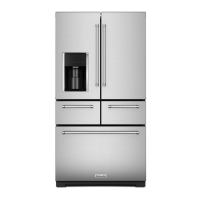
French-Door Boom Mount Refrigerator
Accessing Refrigerator Compartment Components (Continued)
1. Complete the steps 1-5 from removal
instrucons.
2. Fully extend the plaer shelf, depress and release the two
tabs on the underside of the pantry shelf. Remove the shelf
from the cabinet.
3. Li the back of the crisper glass from the underside,slide back
unl the two front edges are released. Remove the crisper
glass.
4. Twist counter-clockwise and remove the water lter.
5. Li and slide the crisper assembly forward unl the rear
center of the assembly clears the base of the air tower cover.
Connue liing and remove the crisper frame assembly.
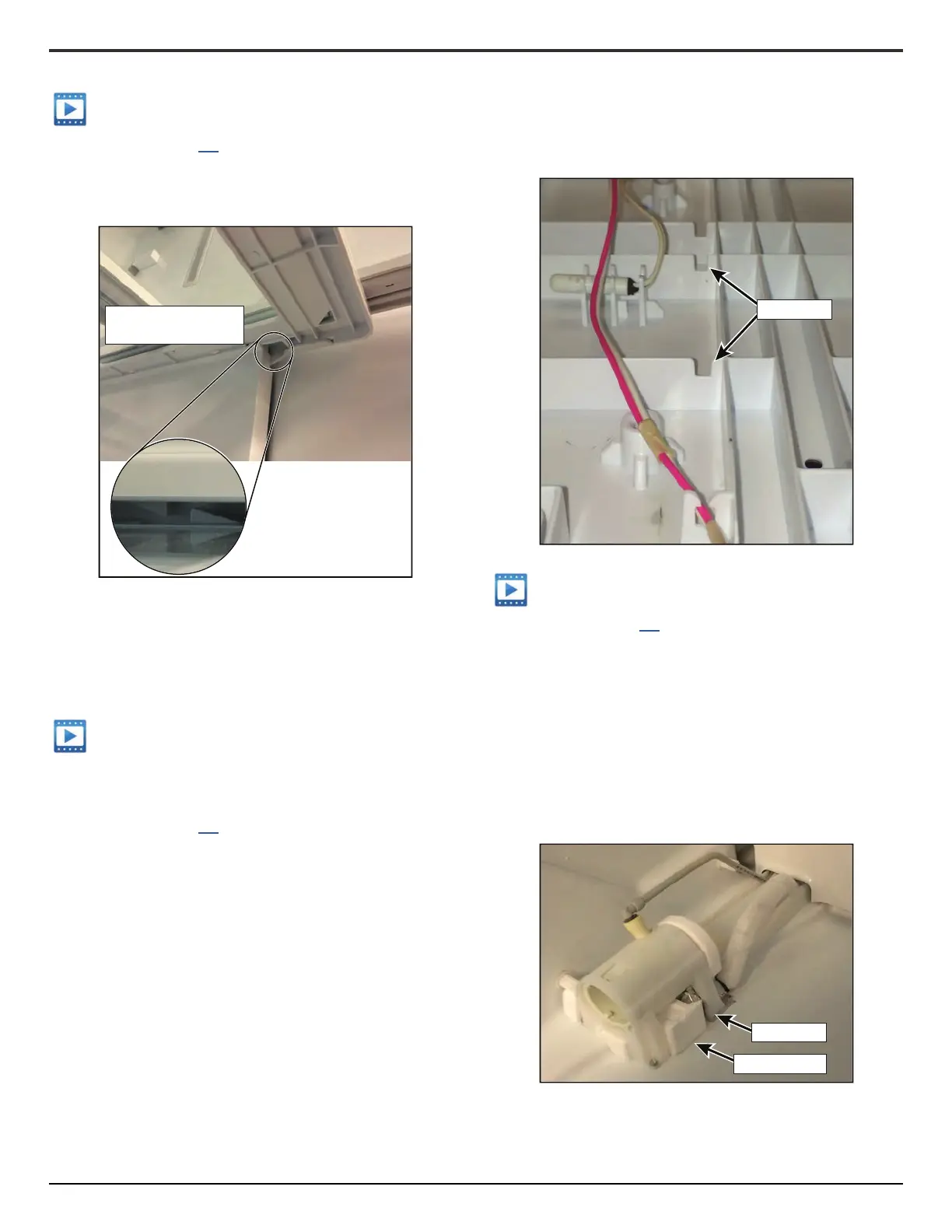
The LED Light and thermistor for the temperature controlled
drawer share the same wiring harness. They are serviced as a
pair.
1. Complete the steps 1-5 from
instrucons.
2. Flip over the Crisper Frame Assembly with the front facing
you.
3. Remove the three Philip screws aaching the le rail to the
boom of the drawer frame.
4. Remove the three Philip screws aaching the right rail to the
top of the drawer frame.
5. Press the tab on the right side of the water lter fascia and
release.
6. Release the two plasc clips holding the right rail to the top
of the drawer frame, and li o the boom of the drawer
frame.
7. Remove the six (6) Philip screws aaching the LED Light to
the drawer frame.
8. Remove the four (4) Philip screws aaching the wire channel
to the drawer frame.
9. Unclip the Thermistor and remove the LED Light, thermistor
and associated wiring.
NOTE: To prevent pinching of the wires,ensure the wiring is
run through the plasc channel in the underside of the
drawer frame during installaon.
1. Complete the steps 1-5 from
instrucons.
2. Remove the two 1/4" screws at the front of the water lter
bracket base.
3. Release the water inlet and outlet lines from the water lter
bracket, and remove the bracket.
4. To remove the water lter housing from the bracket, release
the two plasc tabs at the front top and boom of the
housing, and slide out from the back.
5. When reinstalling the water lter bracket, ensure the under
lter foam insulaon is in place, and the two plasc feet on
the rear of the bracket are inserted into the plasc recess in
the base of the refrigerator liner.
Opening on Underside of
Crisper Assembly
Wire Channel
Plastic Feet
Foam Insulation