samos Safety System
6
© 2010 Wieland Electric GmbH | BA000256 | 12/2012 (Rev. I)
The samos System
Configuration
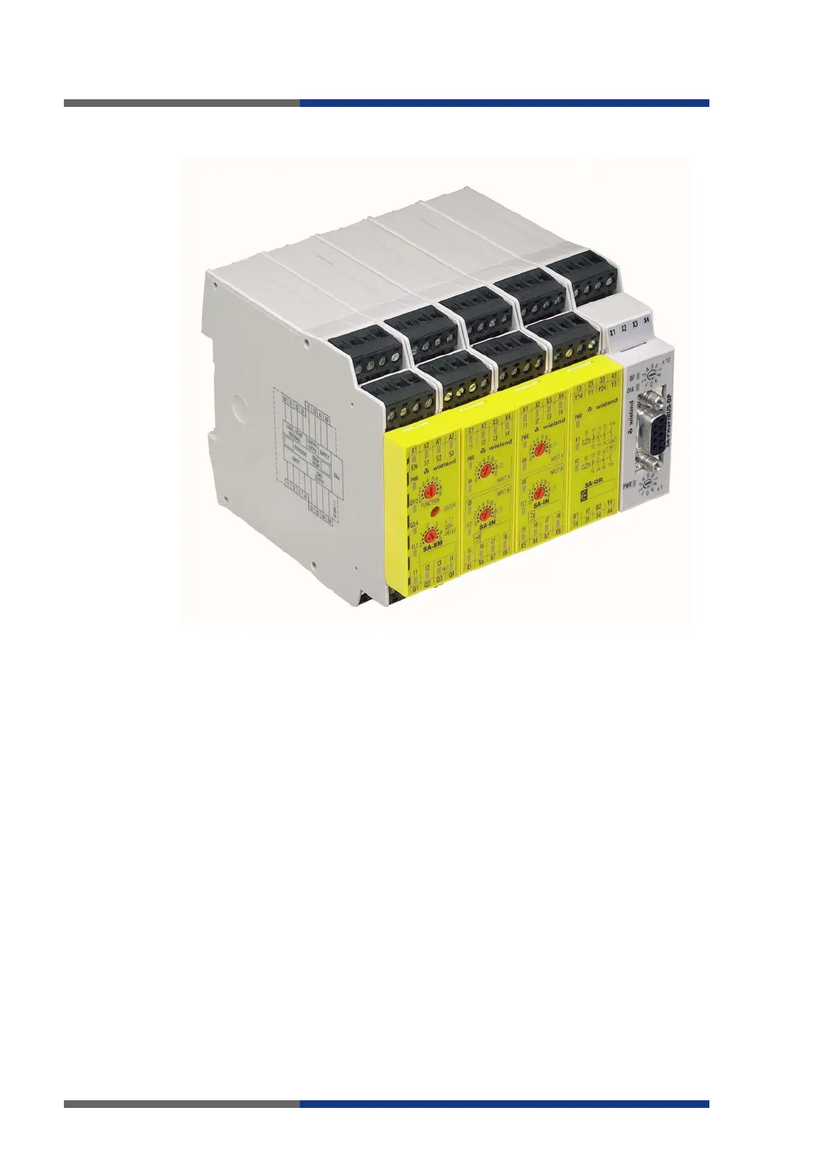
The samos modular safety system is a programmable electronics PE) element of an
electrical/ electronic/programmable electronic system (E/E/PES) as described in IEC/EN
61508/EN 62061. The system comprises base modules, input and output modules, and
bus coupler modules.
The minimum configuration is one SA-BM master base module. You can connect other
active safety modules, passive safety modules and bus coupler modules to the master to
create a system.
Up to 12 active safety modules (SA-IN input modules)
Additionally up to 4 SA-OR passive relay output modules
Additionally 1 bus coupler module
All SA-BM base modules can be expanded with SA-IN inputs and SA-OR relay outputs.
The system groups formed in this way are functionally autonomous and can be wired
together as required.
Structure
In a system the master base module is at the left-hand end, the optional bus coupler
module at the right-hand end. The modules are connected by means of a connector with
proper coding, integrated in the housing. The 24 V power supply is fed in through the
master base module.
.
 Loading...