Gas Supply and Piping (cont.)
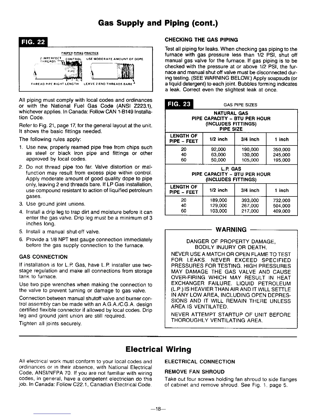
PROPER PIPING PRACTICE
2 IMPERFECT CONTRO L USE MODERATE AMOUNT OF DOPE
THREADS _
THREAD PIPE RIGHT LENGTH LEAVE 2 END THREADS [IARE "
All piping must comply with local codes and ordinances
or with the National Fuel Gas Code (ANSI Z223.1),
whichever applies. In Canada: Follow CAN 1-B149 Installa-
tion Code.
Refer to Fig. 21, page 17,for the general layout at the unit.
It shows the basic fittings needed.
The following rules apply:
1. Use new, properly reamed pipe free from chips such
as steel or black iron pipe and fittings or other
approved by local codes.
2. Do not thread pipe too far. Valve distortion or mal-
function may result from excess pipe within control.
Apply moderate amount of good quality dope to pipe
only, leaving 2 end threads bare. If LP Gas installation,
use compound resistant to action of liquified petroleum
gases.
3. Use ground joint unions.
4. Install a drip leg to trap dirt and moisture before it can
enter the gas valve. Drip leg must be a minimum of 3
inches long.
5. Install a manual shut-off valve.
6. Provide a 1/8 NPT test gauge connection immediately
before the gas supply connection to the furnace.
GAS CONNECTION
If installation is for L.R Gas, have L.R installer use two-
stage regulation and make all connections from storage
tank to furnace.
Use two pipe wrenches when making the connection to
the valve to prevent turning or damage to gas valve.
Connection between manual shutoff valve and burner con-
trol assembly can be made with an A.G.A./C.G.A. design
certified flexible connector if allowed by local codes. Drip
leg and ground joint union are still required.
Tighten all joints securely.
CHECKING THE GAS PIPING
Test all piping for leaks. When checking gas piping to the
furnace with gas pressure less than 1/2 PSI, shut off
manual gas valve for the furnace. If gas piping is to be
checked with the pressure at or above 1/2 PSI, the fur-
nace and manual shut off valve must be disconnected dur-
ing testing. (SEE WARNING BELOW.) Apply soapsuds (or
a liquid detergent) to each joint. Bubbles forming indicates
a leak. Correct even the slightest leak at once.
GAS PIPE SIZES
NATURAL GAS
PIPE CAPACITY - BTU PER HOUR
(INCLUDES FITTINGS)
PIPE SIZE
LENGTH OF
PIPE - FEET 1/2 inch 3/4 inch 1 inch
20 92,000 190,000 350,000
40 63,000 130,000 245,000
60 50,000 105,000 195,000
L.P. GAS
PIPE CAPACITY - BTU PER HOUR
(INCLUDES FITTINGS)
LENGTH OF
PIPE - FEET 1/2 inch 3/4 inch 1 inch
20 189,000 393,000 732,000
40 129,000 267,000 504,000
60 103,000 217,000 409,000
WARNING
DANGER OF PROPERTY DAMAGE,
BODILY INJURY OR DEATH.
NEVER USE A MATCH OR OPEN FLAME TO TEST
FOR LEAKS. NEVER EXCEED SPECIFIED
PRESSURES FOR TESTING. HIGH PRESSURES
MAY DAMAGE THE GAS VALVE AND CAUSE
OVER-FIRING WHICH MAY RESULT IN HEAT
EXCHANGER FAILURE. LIQUID PETROLEUM
(L.P.) IS HEAVIER THAN AIR AND IT WILL SETTLE
IN ANY LOW AREA, INCLUDING OPEN DEPRES-
SIONS AND IT WILL REMAIN THERE UNLESS
AREA IS VENTILATED.
NEVER ATTEMPT STARTUP OF UNIT BEFORE
THOROUGHLY VENTILATING AREA.
Electrical Wiring
All electrical work must conform to your local codes and
ordinances or in their absence, with National Electrical
Code, ANSI/NFPA 70. If you are not familiar with wiring
codes, in general, have a competent electrician do this
job. In Canada: Follow C22.1, Canadian Electrical Code.
ELECTRICAL CONNECTION
REMOVE FAN SHROUD
Take out four screws holding fan shroud to side flanges
of cabinet and remove shroud. See Fig. 1, page 5.
m18m