Thermostat Installation
1. If an old thermostat is being replaced and is in a
satisfactory location and the wiring appears to be
in good condition, use existing wiring. If in doubt, use
new wire.
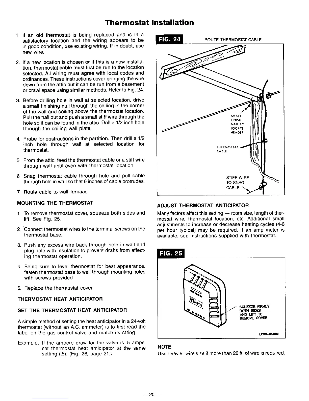
2. If a new location is chosen or if this is a new installa-
tion, thermostat cable must first be run to the location
selected. All wiring must agree with local codes and
ordinances. These instructions cover bringing the wire
down from the attic but it can be run from a basement
or crawl space using similar methods. Refer to Fig. 24.
3. Before drilling hole in wall at selected location, drive
a small finishing nail through the ceiling in the corner
of the wall and ceiling above the thermostat location.
Pull the nail out and push a small stiff wire through the
hole so it can be found in the attic. Drill a 1/2 inch hole
through the ceiling wall plate.
4. Probe for obstructions in the partition. Then drill a 1/2
inch hole through wall at selected location for
thermostat.
5. From the attic, feed the thermostat cable or a stiff wire
through wall until even with thermostat location.
6. Snag thermostat cable through hole and pull cable
through hole in wall so that 6 inches of cable protrudes.
7. Route cable to wall furnace.
ROUTE THERMOSTAT CABLE
Ske,AL t
FINISH
NAIL TO
LOCATE
HEADER
THERMOSIAT
CABLE
STIFF WIRE
TO SNAG
CABLE
MOUNTING THE THERMOSTAT
1. To remove thermostat cover, squeeze both sides and
lift. See Fig. 25.
2. 'Connect thermostat wires to the terminal screws on the
thermostat base.
3. Push any excess wire back through hole in wall and
plug hole with insulation to prevent drafts from affect-
ing thermostat operation.
4. Being sure to level thermostat for best appearance,
fasten thermostat base to wall through mounting holes
with screws provided.
5. Replace the thermostat cover.
THERMOSTAT HEAT ANTICIPATOR
SET THE THERMOSTAT HEAT ANTICIPATOR
A simple method of setting the heat anticipator in a 24-volt
thermostat (without an A.C. ammeter) is to first read the
label on the gas control valve and match its rating.
Example: If the ampere draw for the valve is .5 amps,
set thermostat heat anticipator at the same
setting (.5). (Fig. 26, page 21.)
ADJUST THERMOSTAT ANTICIPATOR
Many factors affect this setting -- room size, length ofther-
mostat wire, thermostat location, etc. Additional small
adjustments to increase or decrease heating cycles (4-6
per hour typical) may be required. If an amp meter is
available, see instructions supplied with thermostat.
SQUEEZE RR_4LY
SOl1"1SIDES
AND UFT 110
R£_IO_,_COVER
t,/_r/...oa.l=t_
NOTE
Use heavier wire size if more than 20 ft. of wire is required.
--20--