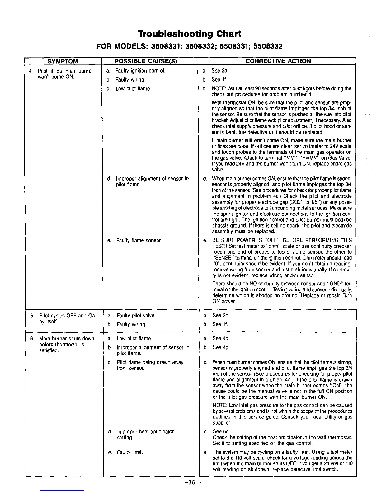
Troubleshooting Chart
FOR MODELS: 3508331; 3508332; 5508331; 5508332
SYMPTOM
4. Pilotlit,butmainburner
won't come ON.
PiJotcycles OFF and ON
by itself,
Main burner shuts down
before thermostat is
satisfied.
POSSIBLE CAUSE(S)
a. Faultyignitioncontrol.
b. Faultywiring.
c. Low pilot flame.
d. Improper alignment of sensor in
pilot flame.
e. Faulty flame sensor.
a. Faulty pilot valve.
b. Faulty wiring.
a. Lowpilotflame.
b. Improperalignmentof sensor in
pilotflame.
c. Pilot flame being drawn away
from sensor
d. Improper heat anticipator
setting.
e. Faultylimit.
a,
b.
C.
d,
e.
CORRECTIVE ACTION
See 3a.
See if.
NOTE:Waitat least90 secondsafter pilotlightsbeforedoing the
check out procedures for problem number 4.
With thermostatON, be sure that the pilot and sensor are prop-
erly aligned so that the pilot flame impinges the top 3/4 inch of
the sensoi_Be sure that the sensor is pushed allthe way into pilot
bracket.Adjustpilot flame with pilotadjustment, if necessary.Also
check inlet supply pressure and pilot orifice, if pilot hOOdor sen-
sor is bent, the defective unit should be replaced.
If main burner still won't comeON, make sure the main burner
orifices are clear:.If orifices are clear, set voltmeter to 24V scale
and touch probes to the terminals of the main gas operator:on
the gas valve.Attach to terminal "MV", "PV/MV" on Gas Valve.
If you read24V and theburner won't turn ON, replace entire gas
valve.
Whenmain burnercomesON,ensure thatthepilot flame isstrong,
sensor is properly aligned,and pilot flame impingesthe top 3/4
inchofthe sensor:(Seeproceduresforcheck for proper pilot flame
and alignment in problem 4c.) Check the pilot and electrode
assembly for proper electrode gap (3/32" to 1/8") or any possi-
bleshorting of electrodeto surrounding metal surfaces.Make sure
the spark ignitor and electrode connections to the ignition con-
trol are tight. The ignition control and pilot burner must both be
chassis ground. _fthere is still no spark, the pilot and electrode
assembly must be replaced.
BE SURE POWER IS "OFF", BEFORE PERFORMING THIS
TEST!! Settest meter to "ohm" scale or use continuity checker.
Touch one end of probes to top of flame sensor, the other to
"SENSE" terminal onthe ignitioncontrol. Ohmmetershould read
"0", continuity should be evident. If you don't obtain a reading,
removewiring from sensor and test both individually, If continui-
ty is not evident, replace wiring and/or sensor.
There should be NOcontinuity between sensor and "GND" ter-
minalontheignition control,Testingwiringand sensorindividually,
determine which is shorted on ground. Replace or repair. Turn
ON power.
a. See 2b.
b. See lf.
a. See 4c.
b. See 4d.
C,
d.
e.
Whenmainburner comes ON,ensurethat the pilot flame is strong,
sensor is properly aligned and pilot flame impingesthe top 3/4
inch of the sensor. (Seeprocedures for checking for proper pilot
flame and alignment in problem 4d.) If the pilot flame is drawn
awayfrom the sensor when the main burner comes "ON", the
cause could be the manual valve is not in the full ON position
or the inlet gas pressure with the main burner ON.
NOTE: Low inlet gas pressure to the gas control can be caused
by several problemsand is notwithin the scope of the procedures
outlined in this service guide Consult your local utility or gas
supplier:
See 6c.
Check the setting of the heat anticipator in the wall thermostat.
Set it to setting specified on the gas control.
The system may be cycling on a faulty limit. Using a test meter
set to the 110volt scale, check for a voltage reading across the
limitwhen the main burner shuts OFF.If you get a 24volt or 110
volt reading on shutdown, replace defeclive limit switch.
--36--