en
44 Installation and operating instructions • Wilo-Control SC2.0-Booster • Ed.01/2023-09
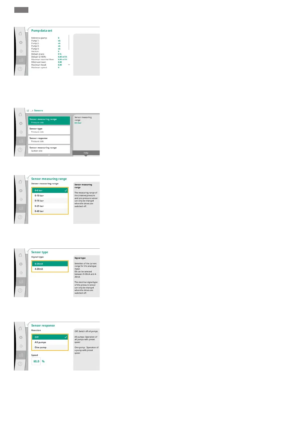
Fig.92: System→Pumps→Pump data set
menu item
For diagnostic purposes, some data points of the pumps present in the system are displayed
here.
7.2.3.2 System -> Sensors menu
Fig.93: System -> Sensors menu item
Settings for the upstream and downstream pressure sensors.
Fig.94: System→Sensors→Sensor measuring
range menu item
Selection of the sensor measuring range of the installed sensor on the output side (discharge
side).
Fig.95: System→Sensors→Sensor type
menu item
Setting for the current range of the end pressure sensor (discharge side). At 4-20mA, monit-
oring for a wire break is possible.
Fig.96: System→Sensors→Sensor response
menu item
In the event of a sensor fault, the system can switch to emergency operation until the sensor
is functional again. It is possible to run one or all pumps constantly at the set speed.