English
Installation and operating instructions Wilo-SiBoost Smart (FC) ... Helix V/... Helix VE/... Helix EXCEL 27
Fig.6a Protection against low water level (WMS) kit
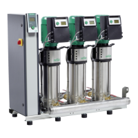
SiBoost Smart Helix V und Helix VE
Fig.6b Protection against low water level (WMS) kit
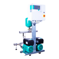
SiBoost Smart Helix EXCEL
14 Low-water cut-out switchgear (WMS),
optional
11 Pressure gauge
16 Draining/venting
17 Stop valve
22 Pressure switch
23 Plug connector
Fig.6c Protection against low water level (WMS) kit,
pin assignment and electrical connection
22 Pressure switch (type PS3)
23 Plug connector
23a Plug connector type PS3-4xx (2-core) (nor-
mally closed contact)
23b Plug connector type PS3-Nxx (3-core)
(changeover contact)
Core colours:
BN BROWN
BU BLUE
BK BLACK
Fig.7 Example of a direct connection (hydraulic
diagram)
Fig.8 Example of an indirect connection (hydraulic
diagram)
24 Consumer connections upstream of the pres-
sure boosting system
25 Diaphragm pressure vessel on the end pressure
side
26 Consumer connections downstream from the
pressure boosting system
27 Infeed connection for system flushing (nomi-
nal diameter = pump connection)
28 Draining connection for system flushing (nom-
inal diameter = pump connection)
29 Pressure boosting system (here with 4 pumps)
30 Diaphragm pressure vessel on the inlet side
31 Unpressurised break tank on the inlet side
32 Flushing apparatus for the inlet connection of
the break tank
33 Building connection to the water supply mains
34 Building connection to the water supply mains
Fig.9 Installation example: vibration absorber and
compensator
A Vibration absorber (screw it into the threaded
inserts provided and secure with it lock nuts)
B Expansion joint with extension limiters (acces-
sory)
C Fixing the pipes downstream from the pressure
boosting system, e.g. with pipe clips (by the
customer)
D Threaded caps (accessory)
Fig.10 Installation example: Flexible connection
lines and fixing to the floor
A Vibration absorber (screw it into the threaded
inserts provided and secure with it lock nuts)
B Flexible connection line (accessory)
BW Bend angle
RB Bend radius
C Fixing the pipes downstream from the pressure
boosting system, e.g. with pipe clips (by the
customer)
D Threaded caps (accessory)
E Floor fixing, with structure-borne noise insula-
tion (by the customer)
Fig.11a Removing the casing
15 Casing (only with pump types Helix EXCEL )
35 Quick-release fastening for casing
A Open the quick-release fastenings
B Swing up the casing hoods
C Remove the casing hoods
Fig.11b Fitting the casing
15 Casing (only with pump types Helix EXCEL )
35 Quick-release fastening for casing
A Fitting the casing hoods (engage the guide
tabs)
B Swing back the casing hoods
C Close the quick-release fastenings
Fig.12 Transport instructions
13 Lifting point for attachment of lifting gear
36 Transport pallet (example)
37 Transport equipment - (example - pallet truck)
38 Transport securing (screws)
39 Hoisting gear (example - spreader beam)
40 Protective wrapper (example)
 Loading...