English
66 WILO SE 05/2015
6.3 Dual pump function/Y-pipe
application
NOTE:
The properties described below are only available if the internal MP
interface (MP = Multi Pump) is used.
• Both pumps are controlled by the master pump.
If one of the pumps malfunctions, the other will run according to the
master’s control settings. In case of a total failure of the master, the
slave pump operates at emergency operation speed.
The emergency operation speed can be set in menu <5.6.2.0> (see
chapter 6.3.3 on page 68).
• The master's display will show the status of the double pump. On the
slave display, ‘SL’ will appear.
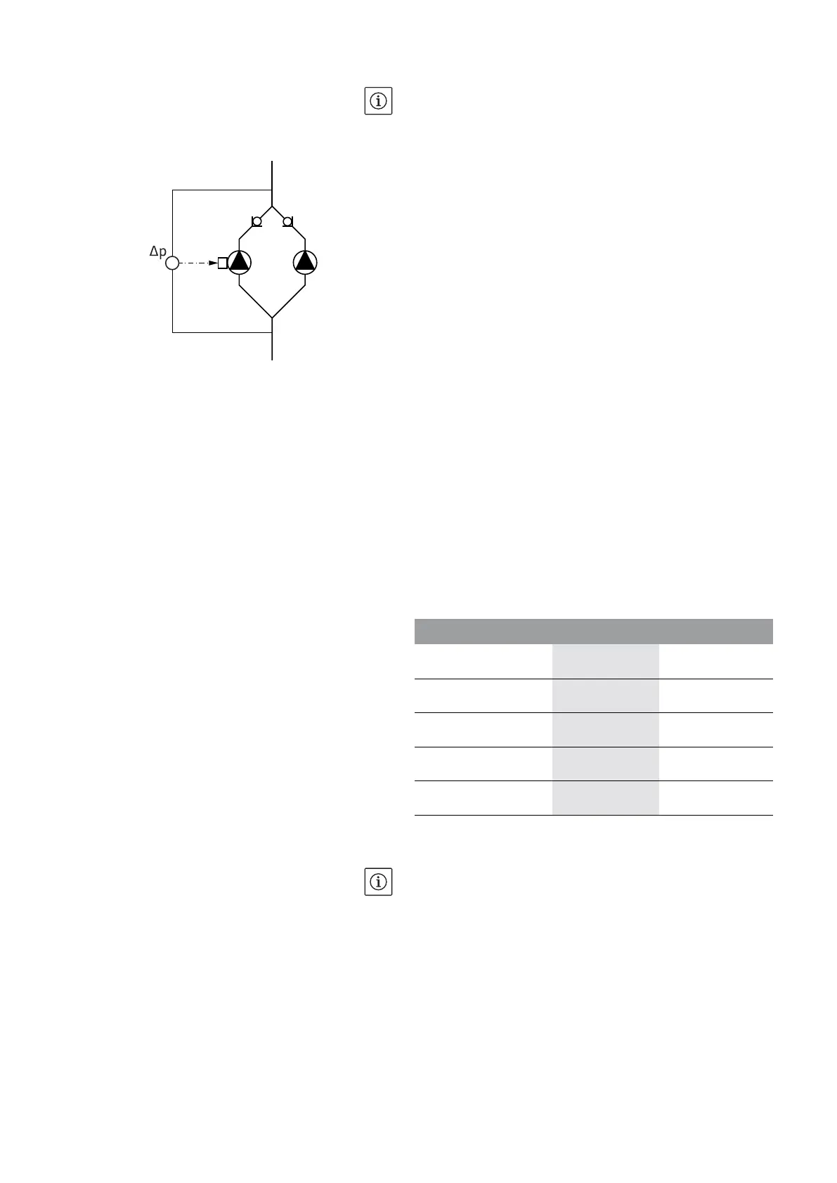
• In the example in Fig. 13, the master pump is the left-hand pump in
the direction of flow. Connect the differential pressure sensor to this
pump.
The measuring points of the differential pressure sensor of the master
pump must be on the suction and pressure side of the double-pump
system in the corresponding collector pipe (Fig. 13).
InterFace-Module (IF-Module) For communication between pumps and the building management
system, one IF-Module (accessories) is required. This is plugged into
the terminal space (Fig. 1).
• The master-slave communication uses an internal interface (terminal:
MP, Fig. 23).
• Normally for double pumps, only the master pump must be equipped
with an IF-Module.
• For pumps in Y-pipe applications in which the electronic modules are
connected to each other through the internal interface, only the mas-
ter pumps require an IF-Module.
Tab. 2: IF-Modules
NOTE:
The procedure and further information for commissioning and con-
figuring the IF-Module on the pump can be found in the installation
and operating instructions of the IF-Module used.
6.3.1 Operating modes
Main/standby mode Each of the two pumps provides the configuration flow rate. The
other pump is available in case of malfunction or runs after pump
cycling. Only one pump runs at a time (see Fig. 10, 11 and 12).
Fig. 13: Example, differential pressure sen-
sor connection
Communication Master pump Slave pump
PLR/Interface converter
IF-Module PLR No IF-Module nec-
essary
LONWORKS network IF-Module LON No IF-Module nec-
essary
BACnet IF-Module BACnet No IF-Module nec-
essary
Modbus IF-Module Modbus No IF-Module nec-
essary
CAN bus CAN IF-Module No IF-Module nec-
essary