English
64 WILO SE 05/2015
• IF-Module LON for connection to the LONWORKS network
• IF-Module BACnet
• IF-Module Modbus
• CAN IF-Module
For a detailed list, consult the catalogue and spare parts documenta-
tion.
NOTE:
IF-Module may only be plugged in when the pump is de-energised
(voltage-free).
6 Description and function
6.1 Description of the product The pumps described here are single-stage low-pressure centrifugal
pumps with a compact construction and a coupled drive. The pumps
can be installed both directly as a pipe installation pump in a suffi-
ciently anchored pipe or placed on a foundation base.
The pump housing of the IP-E and the DP-E is configured in an in-line
design, i.e. the flanges on the suction and pressure sides are located
in the same axis. All pump housings are provided with pump support
feet. Installation on a foundation base is recommended.
NOTE:
Blind flanges, which allow the motor impeller unit to be replaced even
in double pump housing, are available for all pump types/frame sizes in
the DP-E series (see chapter 5.4 “Accessories” on page 63). A drive can
therefore remain in operation while replacing the motor impeller unit.
Functional assemblies
Electronic module The electronic module controls the speed of the pump within the
control range that can be adjusted by the setpoint.
The hydraulic output is controlled by differential pressure and the set
control mode.
In all control modes, however, the pump adapts itself continuously to
the changing power requirements of the system, which is the case
especially when thermostatic valves or mixers are used.
The basic advantages of the electronic control are:
• Energy saving at the same time as reduced operating costs
• Reduced number of differential pressure valves required
• Reduction of flow noise
• Adaptation of the pump to changing operating requirements
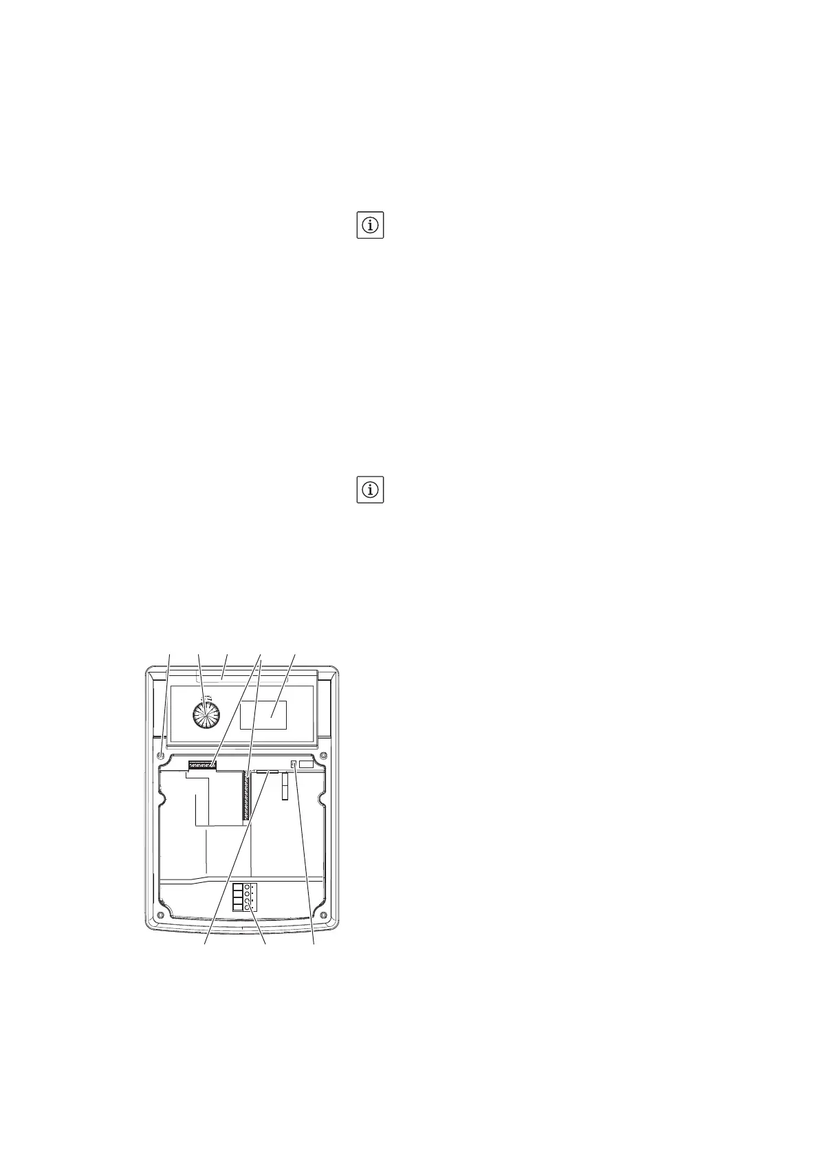
Legend (Fig. 9):
1 Attachment point, cover
2 The red button
3 Infrared window
4 Control terminals
5 Display
6 DIP switch
7 Power terminals (mains terminals)
8 Interface for IF-Module
Fig. 9: Electronic module
12345
768