English
72 WILO SE 05/2015
7.1 Permitted installations position and
change of the arrangement of
components before the installation
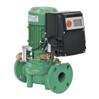
The component arrangement concerning the pump housing is pre-
installed as a factory setting (see Fig. 17) at can be changed if need be
at the operating location. This can be necessary, for example, to:
• Ensure the venting of the pumps
• Make operation easier
• Prevent impermissible installation positions (i.e. motor and/or elec-
tronic module downwards)
In most cases, it is enough to rotate the motor impeller unit relative to
the pump housing. The possible arrangement of components is the
result of the permitted installation positions.
Permitted installation positions with
horizontal motor shaft
The permitted installation positions with horizontal motor shaft and
electronic module facing up (0°) are shown in Fig. 18. The permissible
installation positions with electronic module mounted on the side
(+/–90°) are not shown. Any installation position is allowed except for
“electronic module facing down” (–180°). The venting of the pump is
only ensured when the air vent valve is pointing upwards (Fig. 18,
Item 1).
Only in this position (0°) can condensate be directed away via an
existing drilled hole, pump lantern and motor (Fig. 18, Item 2).
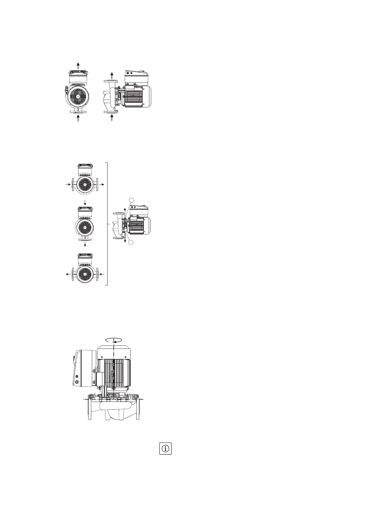
Permitted installation positions with
vertical motor shaft
The permitted installation positions with horizontal motor shaft are
shown in Fig. 19. All installation positions except for “motor facing
down” are allowed.
Depending on the pump type, the motor impeller unit can be arranged
in four or eight different positions, relative to the pump housing (each
shifted by 90° or 45°).
Changing the component arrange-
ment
NOTE:
To make the installation work easier, it can be helpful to install the
pump in the piping without electrical connection and without filling
of the pump or system (see chapter 10.2.1 “Replacing the mechanical
seal” on page 98 for installation steps).
Fig. 17: Arrangement of the components
upon delivery
Fig. 18: Permitted installation positions
with horizontal motor shaft
1
2
Fig. 19: Permitted installation positions
with vertical motor shaft
4 x 90°