23
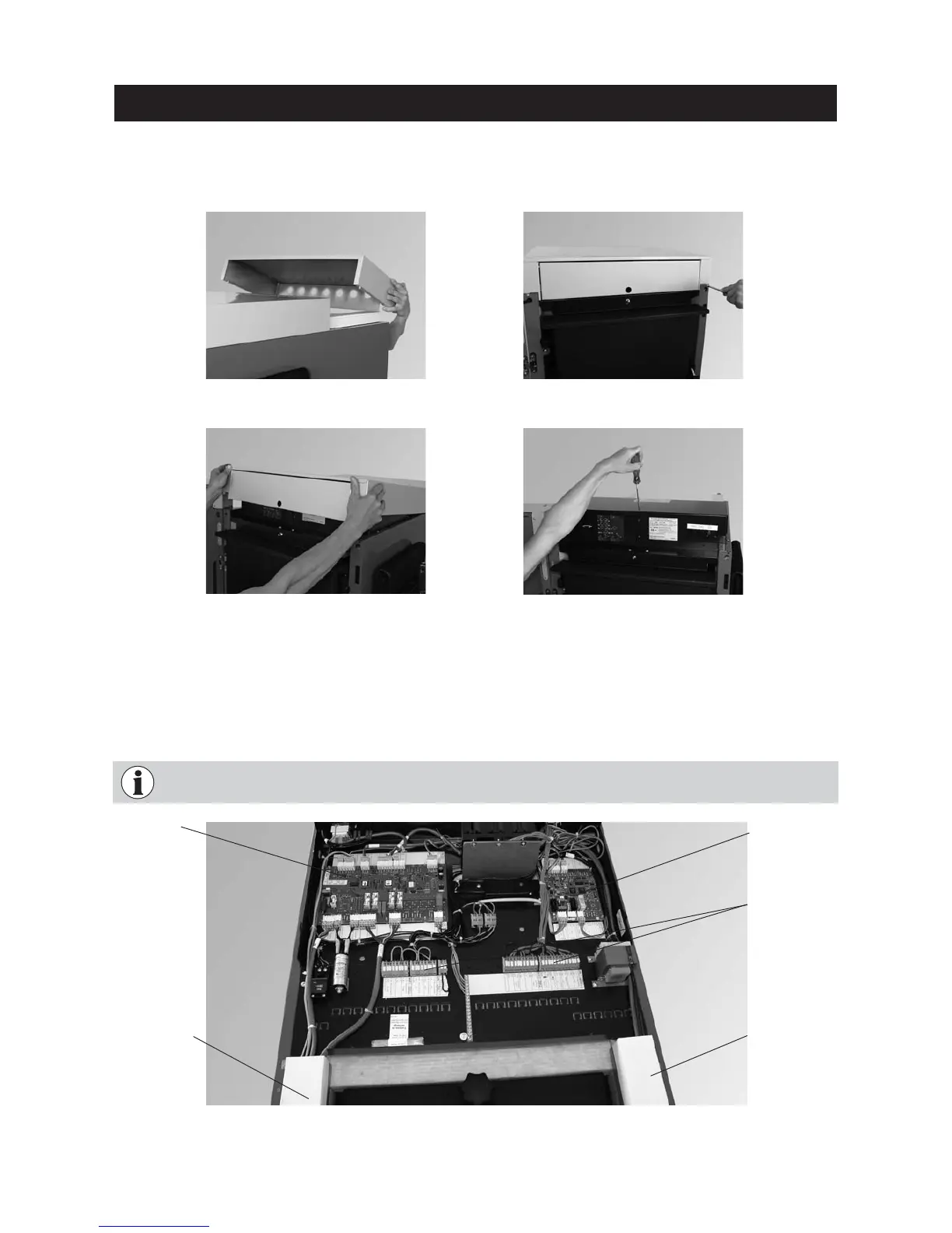
Be sure to note the separate wiring of the extra-low voltage line (sensor) and low-voltage line
(230 V AC)! Route cables in the cable ducts available – Fig. 46.
Cable duct
Low-voltage
(230 V AC)
– In the control panel, fit the plugs for the lambda sensor and air control to the extra PCB or automatic firing
devices. Cables and plugs are inscribed – Fig. 48.
– The connections for the MES system control are on the terminal blocks (screwless spring-type terminals) at
the rear in the control panel and should be connected with fine-wire PVC sheathed cables – Fig. 46.
Fig. 45 Loosening 1 screw at top and
removing the control panel cover
For the Electrician
Fig. 43 Loosening 2 screws at front
Fig. 44 Lifting boiler cover at front and
pulling off to the front
– Take off boiler cover at rear (Fig. 42), loosen 2 screws from boiler cover at front (Fig. 43) and lift up cover
and pull off to the front – Fig. 46.
– Loosen 1 screw on top of control panel cover and take off cover – Fig. 47.
Fig. 46 Control panel open, connecting plugs – rear view
Cable duct
Extra-low volt-
age
(sensor)
Fig. 42 Removing the rear boiler cover
Automatic fir-
ing device
(main board)
Extra PCB
MES terminal
blocks