For connection of weather station.
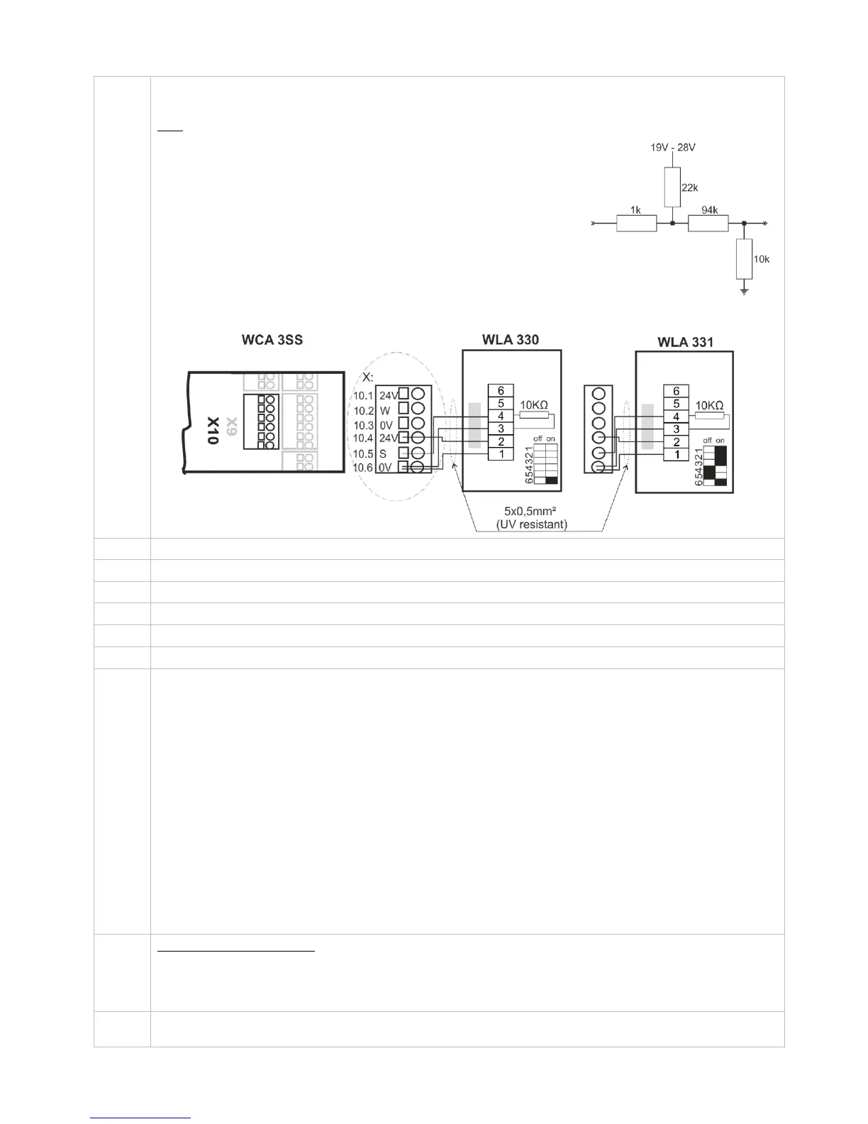
Connection of wind / rain sensors type WLA 330 or rain sensor WLA 331.
Data
10.1 24V UPS (only available with Plus version)
10.2 Wind speed (only available with Plus version)
10.3 GND / 0V (only available with Plus version)
10.4 24V
10.5 Rain (10kΩ resistor is to be inserted when a rain sensor is not connected)
10.6 GND / 0V
With the default values are input:
”Active” if the contact resistance is smaller than 4kΩ
”Inactive” if the contact resistance is bigger than 8kΩ.
For values between 4 and 8kΩ the result will depend on the supply voltage.
Input has pull up approx. 1mA. (min 0.7mA, max 1.4mA)
Example: Wind/rain and rain sensors
WLA 330 and WLA 331– the settings of the sensors are set on the sensor.
Connection for power supply
Connection for battery (power back-up)
USB host. Used for event log creation for e.g. error detection
USB device. Used for remote control and update of firmware
Reset / Programming (used for firmware updates)
2 DIP switch blocks with 8 DIP switches each
1.1 – 230V power failure
1.2 – Momentary action CLOSE (comfort ventilation)
1.3 – Momentary action OPEN (comfort ventilation)
1.4 – System fault triggers alarm
1.5 – VdS triggering by alarm
1.6 – Smoke detector – CLOSE (primarily used in Switzerland)
1.7 – 24V / 48V input active (primarily used in France)
1.8 – Actuators with higher run time than 61sec (both closing and opening speed)
2.1 – Run time limitation (comfort ventilation)
2.2 – Run time limitation (comfort ventilation)
2.3 – Run time limitation (comfort ventilation)
2.4 – Re-activation of run time limitation (OPEN)
2.5 – 20A on output X1
2.6 – Simple cable monitoring
2.7 – No grace timer
2.8 – Disable low stand-by power
See section 11 for further detail
Shows the status of the panel
Red = alarm
Yellow = fault
Green fast flickering = all OK (CPU working), Green constant = CPU communication stopped (possible reset or
contact WindowMaster)
Close / open all windows. When pressed together right after power has been connected the panel configures /
registers connected components.
Input circuit (simplified)