Re-activation of run
time limitation
(OPEN)
ON: If DIP switch 2.1 - 2.3 is activated, the run
time limitation can be reactivated.
OFF: normal
If DIP switch 2.1 - 2.3
is not activated, there
is no function on DIP
switch 2.4.
20A actuator output
on X1
ON: actuator output X1 is 20A and actuator
output X2 is 10A.
OFF: both actuator outputs (X1 & X2) are 10A
Type of motor line
cable monitoring.
ON: simple monitoring. Short circuit between
all wires or cable break is detected.
OFF: Full monitoring. Short circuit between
any of the wires and break of any of the wires
is detected.
Deactivate grace
timer (manual
operation after an
safety command)
ON: Deactivate grace timer
OFF: Use standard grace timer 30 sec.
(default)
The grace timer is a safety feature that gives
the user the possibility to interfere with
automatic (non smoke) safety commands for
30 sec. After the 30 sec. has ran out the
actuator will return to the automatic position.
Smoke commands (Alarm/Reset) always has
first priority.
Disable low
stand-by power
Disalbes low power
consumption
ON: Low power mode is disable. Main power
supply is kept on.
OFF: Low power mode is enabled. Main power
shuts off, but turns on every 90sec due to
cable monitoring.
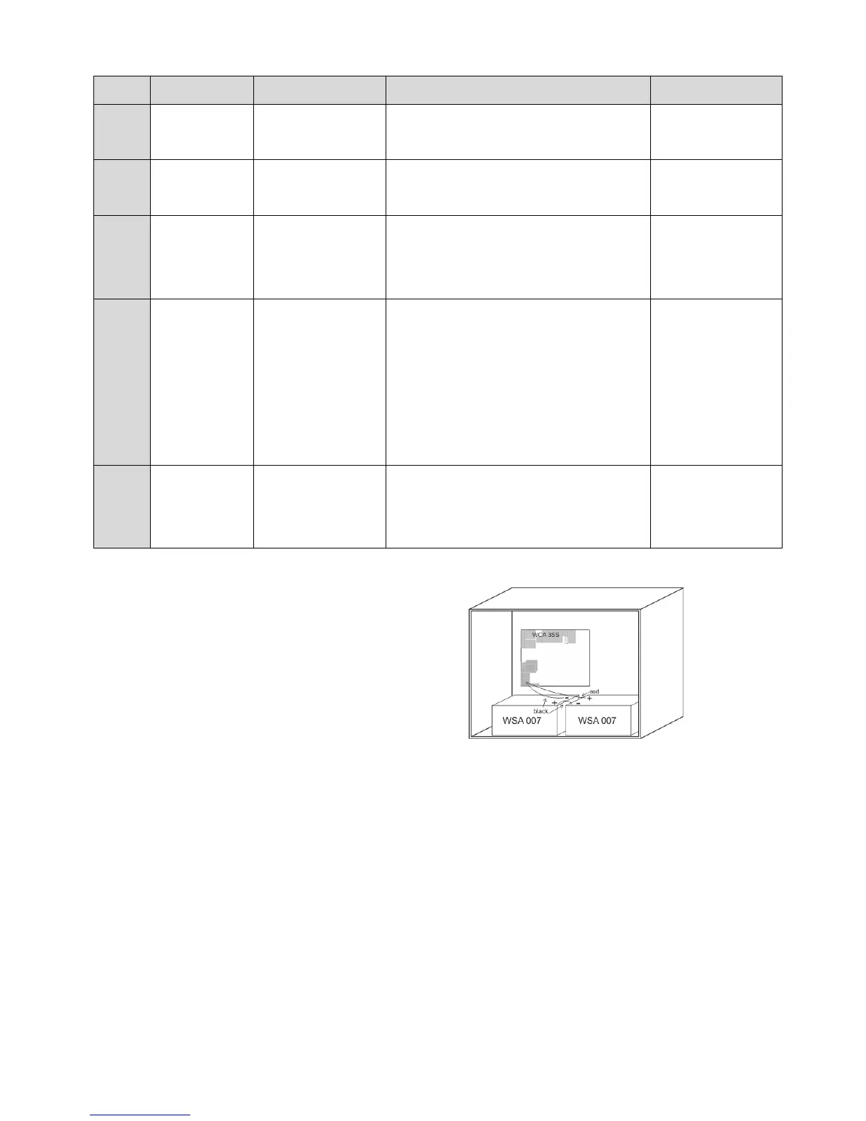
Connect 2 pcs. back-up batteries type
WSC 007 for WSC 310 and type WSA 012
for WSC 320.
See section 17 “Maintenance” for further
information.
Example of WSC 310 panel with back–up batteries.
13 Configuration of panel
The smoke panel is configured by pressing the two keys ”↑” and ”↓” on the main card, at the same time for 5-10 seconds.
The smoke panel must be configured
- After re-installation, changes, or change of actuators
- When / if MotorLink
®
actuators are connected
- If the cables have been moved
- When components are removed from the panel
- If there has been a fault on the WSK-Link™. Error blink sequence 6, see section 14.
Note, during reconfiguration both actuator outputs can be activated in both directions.
If the yellow diode on the main card blinks after a configuration, an error has occurred in the configuration, see section “Fault
detection via LED” for identification of errors.
13.1 Motor lines – motor groups – smoke zones
All the components connected to the Standard panel are automatically assigned to groups and zones:
- motor lines are assigned to motor groups
- motor groups are assigned to smoke zones
- break glass units and smoke detectors are assigned to smoke zones