WSC 310: 300 x 400 x 120mm (HxWxD)
WSC 320: 300 x 400 x 210mm (HxWxD)
WSC 310: 6kg no batteries, 10.8kg with batteries (2 x WSA 007)
WSC 320: 8.6kg no batteries, 16.6kg with batteries (2 x WSA 012)
Approved and certified according to EN 12101-10
CompactSmoke™ smoke ventilation panel with WSA 501 (10kΩ resistors, 10
pcs.) and 2 pcs. end of line module WSA 510. Back-up batteries included.
We reserve the right to make technical changes
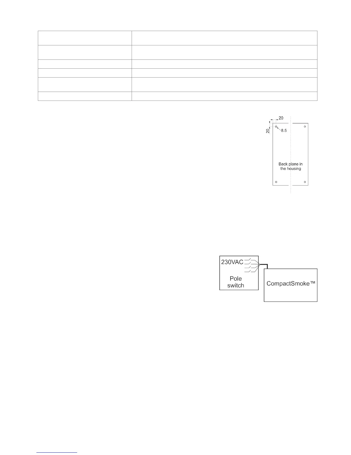
The smoke ventilation panel is fixed to the wall through the Ø8.5mm holes in the back plane of the
housing.
If the panel is fixed in different way, the holes are to be blinded with the 4 blind grommets, this way
the IP class is maintained.
The door is turnable.
When turning the door also move the blind grommets to the new holes.
The smoke ventilation panel is to be located in a safe place, protected from the effects of fire and
smoke.
7 Installation
7.1 Cable routing
For cable routing we recommend the use of fire protected cables retaining their function E90 or E30.
See also chapter 8 “Cable dimensioning” in this instruction.
However, this has to be agreed with the Engineer or, if necessary, with the local fire protection department.
Do not reduce the cable cross sections specified in the cable lengths table.
All cables of the control (except the mains supply cable) carry 24V DC and have to be routed separate from the mains supply
cable.
Adhere to the pertinent national and local regulations when routing the cables.
Lead the connection cables into the housing of the control panel from above
and the cable glans shall comply with fire class V-1 (IEC/EN 60695-11-20 / UL
94) or higher and be in accordance with national and local regulations.
Ensure that the mains cable can be switched via an external or customer-supplied
two-pole switch element or a switch element controlling all poles – see drawing.
7.2 Cables into housing
All connection terminals (except the mains terminals) are of the plug-in type.
Connect the connection cables in accordance with the terminal plan. Ensure that the connections are made correctly.
Incorrect cable clamping, mixing up numbers or colours could lead to malfunctions of the control panel or of the external
components.
Ensure that the electrical cables are always routed according to the valid national and local regulations.
7.3 Connection of safety earth wire and 230V AC
See chapter 10 ‘Description of cards’, section 10.1 for further description.
7.4 Installation of the break glass unit, ventilation keypad and smoke detector
Ensure that the break glass unit and the ventilation buttons are visible and well accessible. Do not install behind protruding
walls, door panels or hidden by the building structure.
Note: Installation height of the break glass unit 1.5 – 1.7m above floor.
Install the smoke detectors in accordance with their enclosed instructions