23
13.1.5 Local input
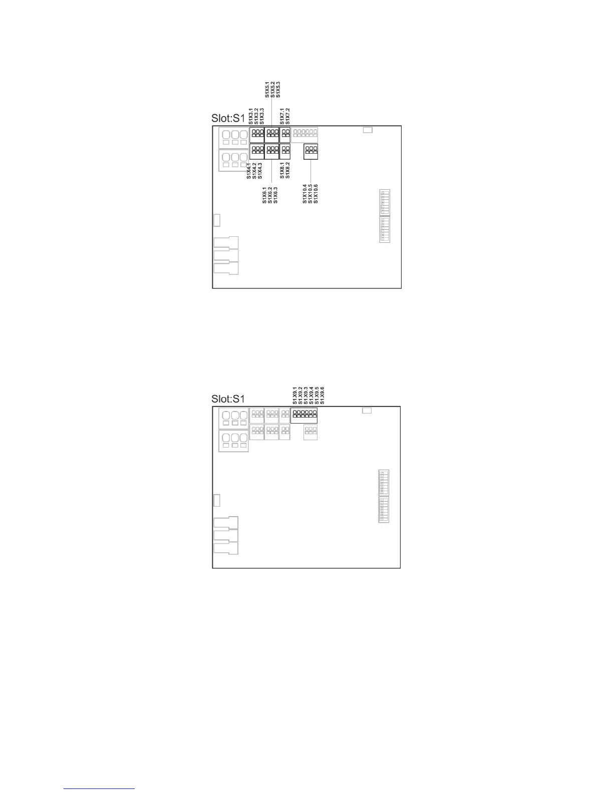
The seven inputs on the Standard version panels are pre-configured with the functions as shown below.
Inputs on the smoke ventilation panel
S1 X3 – X4 Comfort keypads configuration
S1 X5 – X6 Break glass units configuration
S1 X7 Smoke detector configuration
S1 X8 24V / 48V configuration
S1 X10 Weather station with wind direction configuration (only possible with the Plus version)
13.1.6 Local output
The output on the Standard version panels are pre-configured with the functions as shown below.
Smoke ventilation panel
S1 X9.1 – X9.2 Fault signal to fire alarm system configuration
S1 X9.3 – X9.4 Alarm triggering in smoke zone 1 configuration
S1 X9.5 – X9.6 Alarm triggering in smoke zone 2 configuration
14 Fault detection via LED
14.1 Fault detection on the smoke panel
In case of error on the panel, the yellow diode on the main card will blink and via blink sequence indicate an error message.
Depending on the type of error message will consist of 2 or 3 blink sequences, separated by a seconds pause. The first blink in an
error message has a duration of one second, and thereby indicating when the error message (1
st
blink sequence) begins. The
remaining blinks of the error message has a duration of 0.5 seconds. The error message is repeated until the error has been
rectified. Between 2 error messages there is a pause of 2 sec.