Maintenance1132−2/A1
RT-flex58T-E
Winterthur Gas & Diesel Ltd.
10/ 14
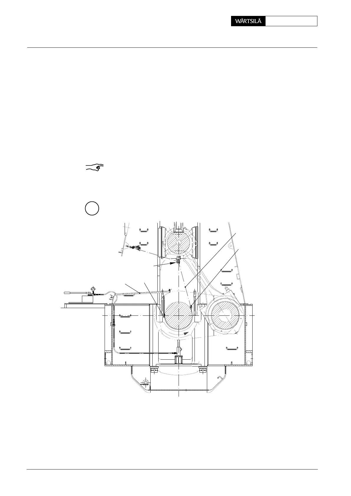
4.6 Turning out the main bearing shells No. 2 and following
D Crankshaft lifted up by approx. 0.2 mm (see paragraphs 4.1 and 4.2).
⇒ Install roller support 94117 on the column.
⇒ Attach manual ratchet ’H1’ with rope 94120F to lifting yoke 94119 via roller
support.
D Turning-out device 94118A and lifting yoke 94119 are mounted in the same
way as described in paragraph 4.4.
⇒ With manual ratchet ’H1’ pull bearing shell slowly out from the bearing girder
until both ends of the bearing shell are free (no meshing), check!
⇒ Remove lifting yoke.
Remark: If a bearing shell jams during turning out, lifting yoke 94119 must be fas-
tened to the two opposite wire ropes of turning-out device 94118A. Subsequently
draw the bearing shell back to the initial position until the bearing shell is freed.
M
94119
94120F
94117
94142
H1
94118A
WCH01015
Removal and Fitting of a Main Bearing
2013 / V2