Maintenance
2124−2/A1
RT-flex58T-E
Winterthur Gas & Diesel Ltd.
3/ 7
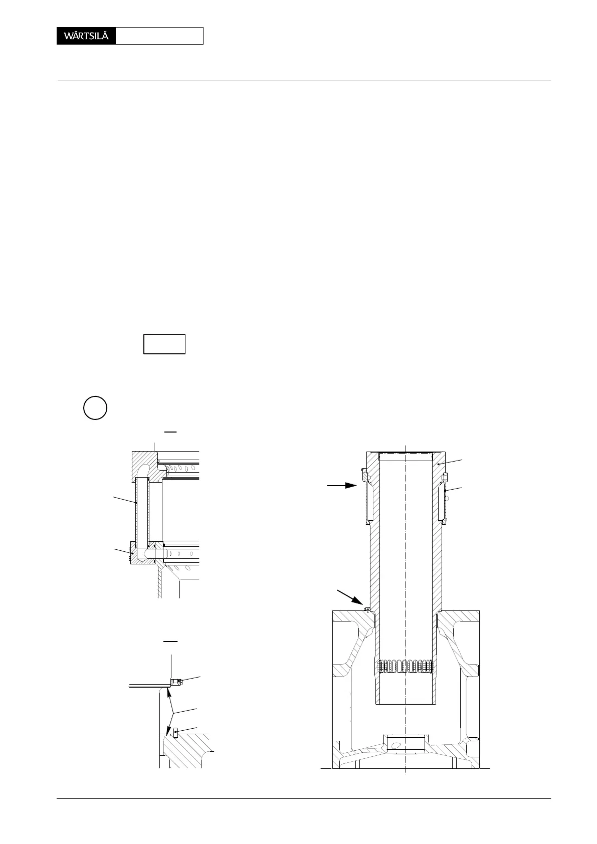
2.2 Removal
A cylinder liner can be removed by crane and lifting gear.
⇒ Lift the cylinder liner on shackle GF 94202M provided in the center of the
device (Fig. ’B’).
2.3 Fitting
⇒ Place the device GF 94201 diagonally onto the cylinder liner 2 in accordance
with paragraph 2.1.
⇒ Clean the seating surfaces ’AF’ on cylinder liner 2 and cylinder block 1. Apply
a non-hardening sealing compound.
⇒ Turn the cylinder liner 2 and align the centring hole in holder 14 with the cent-
ring pin 9 of the cylinder block 1. Lower the cylinder liner.
⇒ Fit the connection pieces 7 with transition tubes 6 to water guide jacket.
⇒ Fit all lubricating quills and connect their pipings.
Actuate the cylinder lubricating pump until oil emerges from all the lubricating
grooves in the corresponding cylinder liner (see Operating Manual 2138−1 ’Func-
tion check’).
2
3
I
6
WCH01000
FUEL SIDE
II
I
AF
II
9
14
7
C
Cylinder Liner
Removal and Fitting
2013
CHECK