Maintenance
2722−1/A2
RT-flex58T-E
Winterthur Gas & Diesel Ltd.
5/ 12
5. Assembling an injection valve
5.1 Determining of the relevant tightening torque with displaced pivot point
Due to the displaced pivot point, make sure that the coupling nut 11 and clamping
nut 15 is tightened only to the reduced tightening torque as explained below.
The set torque ST can be determined with the following data:
ST =
TT x D1
D2 + D1
ST (Nm) TT (Nm) D1 (mm) D2 (mm)
Coupling nut (11) AF55 89 100 530 65
Clamping nut (15) AF41 172 190 530 55
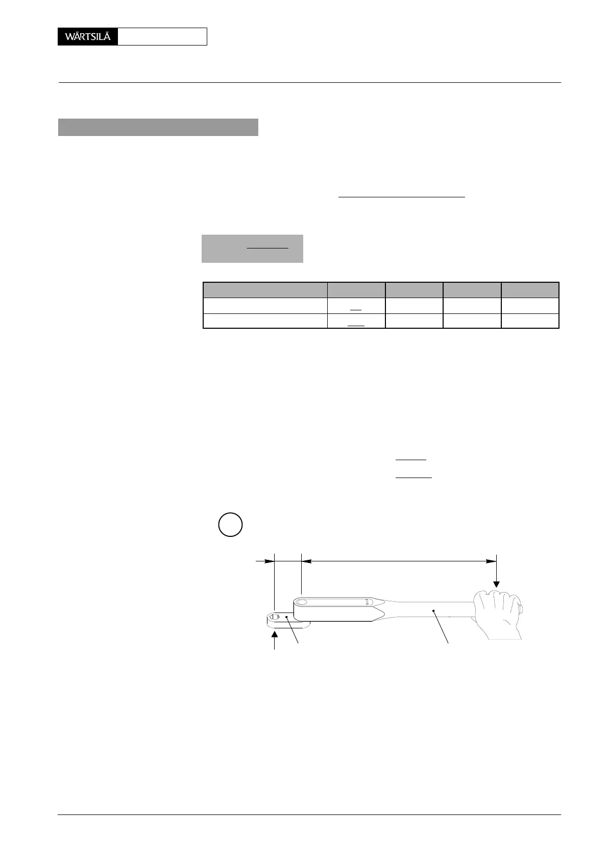
− ST = Set Torque to be set on the scale of torque spanner
− TT = Tightening torque specified for coupling nut and clamping nut
− D1 = Distance from middle of square drive to middle of handgrip
− D2 = Distance from middle of square drive to middle of coupling nut
and clamping nut
Coupling nut (11) AF55 100 x 530 : 65 + 530 = 89 Nm
Clamping nut (15) AF41 190 x 530 : 55 + 530 = 172 Nm
C
94011A94269C−55
D2 D1
DISPLACED
PIVOT POINT
94269C−41
ER-3 / 2013-08
Injection Valve: Checking, Dismantling, Assembling and Adjusting Injection Valve with FAST