Maintenance2722−1/A2
RT-flex58T-E
Winterthur Gas & Diesel Ltd.
10/ 12
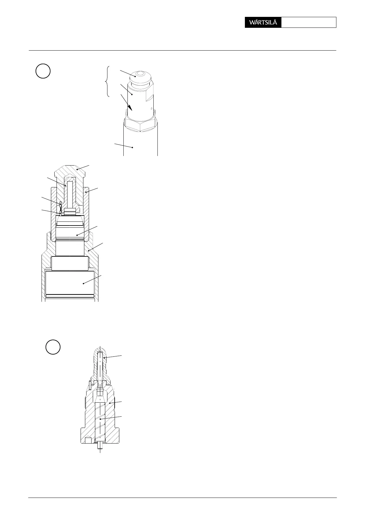
7.2 Installation
⇒ Make sure that the needle 5, is removed from the
nozzle body 4, see Fig. E.
⇒ Attach the nozzle body 4 with coupling nut 6 to the
injection valve 1 on the injection test bench.
⇒ Make sure the dowel pin 13 is installed.
⇒ Screw the guide bush A2 of tool 94278B onto the
nozzle body 4.
⇒ Put the nozzle tip 12 into mounting cylinder A1 of tool
94278B and align the recess in the nozzle tip with the
dowel pin A3.
⇒ Guide the mounting cylinder A1 with the inserted
nozzle tip 12 into the guide bush A2.
⇒ Turn the mounting cylinder A1 until the recess of the
nozzle tip aligns with the dowel pin 13.
⇒ The mounting cylinder lowers a little bit and can not
be turned anymore.
⇒ Use copper or rubber hammer to tap the mounting
cylinder A1 fully down.
⇒ Screw the guide bush A2 out to remove the nozzle
assembly tool 94278B.
⇒ Remove coupling nut 6 and nozzle body 4.
⇒ Use clean diesel oil, or clean kerosene to clean the
needle 5.
⇒ Use a clean, low-pressure air supply to dry the nee-
dle 5.
⇒ Put the needle 5 into the nozzle body 4 / nozzle tip
12. Make sure that the the needle moves freely.
⇒ Assemble the injection valve, see paragraph 5.2.
2015−08
Injection Valve: Disassemble, Checks, Assemble Injection Valve with FAST
12
A1
6
94278B
A2
A2
A1
6
A3
A3
13
4
3
WCH02908
WCH02908
F
G
5
12
4