Maintenance
1132−2/A1
RT-flex58T-E
Winterthur Gas & Diesel Ltd.
3/ 14
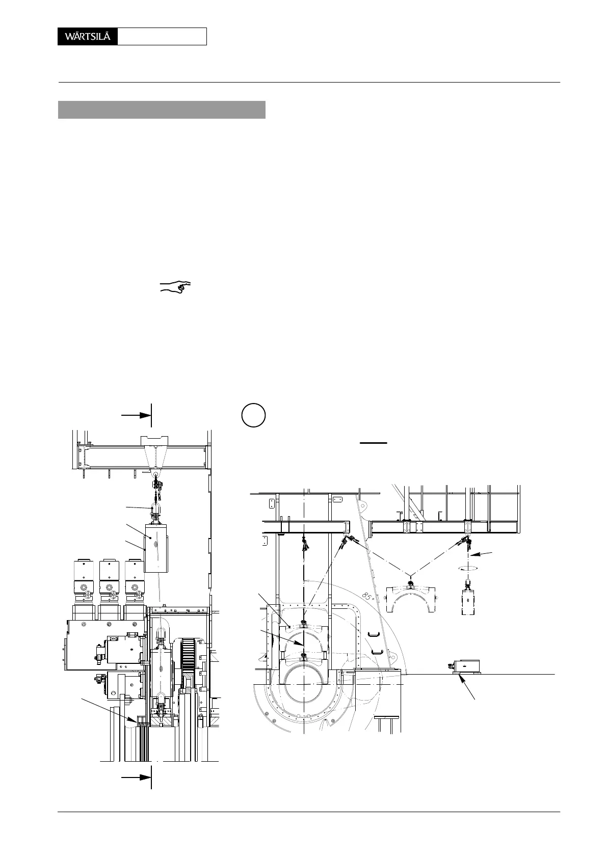
3. Removal of main bearing cover
3.1 Removal of bearing cover No. 1
⇒ Turn crank of Cyl. No.1 to exhaust side approx. 85_ after T.D.C..
⇒ Remove upper part of oil baffle and upper casing at the driving end.
⇒ Protect slinger rings on the crankshaft.
⇒ Loosen nuts for elastic studs hydraulically (see 1132−1).
⇒ Place device 94111 with eyelet 94120 as described in section 2.
⇒ Lift bearing cover over the elastic bolts using rope 94120B and manual ratchet
’H1’.
Remark: Oil bore 7 in bearing girder 6 must be closed off immediately after lifting
the bearing cover, to prevent any dirt from entering (Fig. ’A’).
⇒ Remove the bearing cover from the column.
⇒ Connect ratchets ’H3’ with rope 94120B and ’H2’ and lift the bearing cover out
of the flywheel area.
⇒ Carefully put the bearing cover in horizontal position on wooden underlay
’WU’. Make sure the protruding bearing shell 10 does not get damaged.
C
I - I
I
I
H1
94120B
94111
2
PR
H2 H3
H2
WU
WCH01010
EXHAUST
SIDE
DRIVING END
94120B
94120
10
Removal and Fitting of a Main Bearing
V2 / 2013