Maintenance1132−2/A1
RT-flex58T-E
Winterthur Gas & Diesel Ltd.
4/ 14
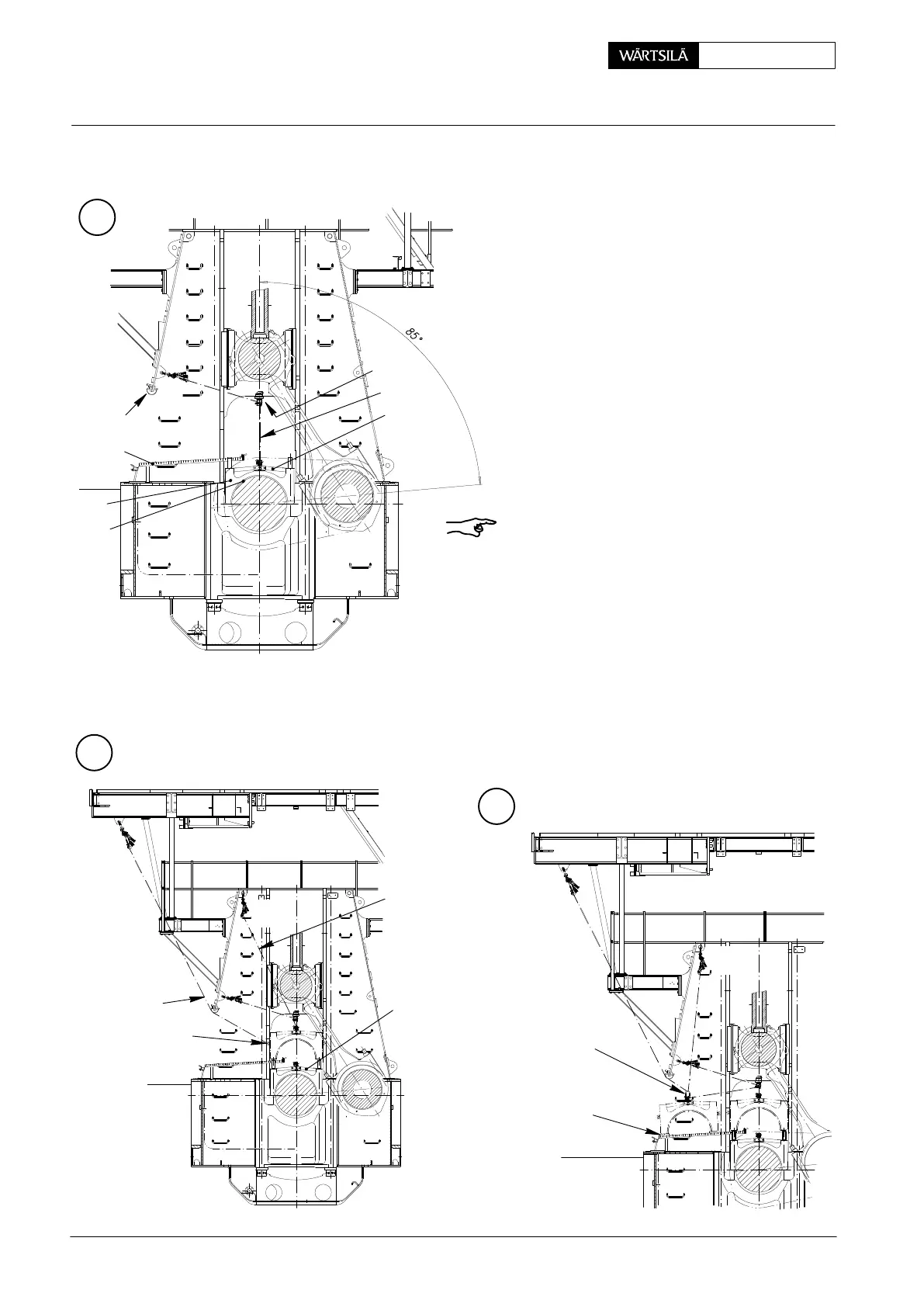
3.2 Removal of bearing cover No. 2 and following
⇒ Turn corresponding crank to exhaust side ap-
prox. 85_ after T.D.C.
⇒ Install working platform 94142 (see 3301−1).
⇒ Remove nuts for elastic studs (see 1132−1).
⇒ Place lifting device 94111 (without eyelet
94120) as described in section 2.
⇒ Attach deviation pipe GF 94117A and install
roller support 94117 on the column (Fig. ’D’).
⇒ To protect upper bearing shell 10, provide
protection at the side of adjacent crank webs.
⇒ Attach manual ratchet ’H1’with rope 94120F
to the column wall and lift the bearing cover 2
via roller support 94117 over the elastic
studs.
Remark! Oil bore 7 in bearing girder 6 must be
closed off immediately after lifting the bearing cov-
er, to prevent any dirt from entering (Fig. ’A’).
⇒ Screw eye bolt ’RC’ into the bearing cover
and connect it with rope 94120E to manual
ratchet ’H4’ (Fig. ’E’).
⇒ Attach manual ratchet ’H2’ with rope
94120G to lifting device 94111.
⇒ Lift bearing cover by means of manual
ratchets ’H1’ and ’H2’ over the crank web
(Fig. ’E’) and place it with manual ratchet ’H4’
on working platform with a wooden underlay
’WU’ (Fig. ’F’).
D
E
F
H4
94111
94117
GF 94117A
94142
10
2
H1
H4
94120E
RC
H1
94120F
94120G
H2
H2
94120
WU
H1
EXHAUST
SIDE
94111
WCH01010
Removal and Fitting of a Main Bearing
2013 / V2