Page 23
Winkhaus STV
Operating Manual EAV 0124653 0505
Subject to technical changes
Winkhaus STV GmbH & Co. KG · Berkeser Str. 6 · D-98617 Meiningen · Germany · www.winkhaus.de · stv@winkhaus.de
NOTICE!
Do follow the relevant installation instructions of the additional applications!
• Put the cover back on the housing and lock and screw it down.
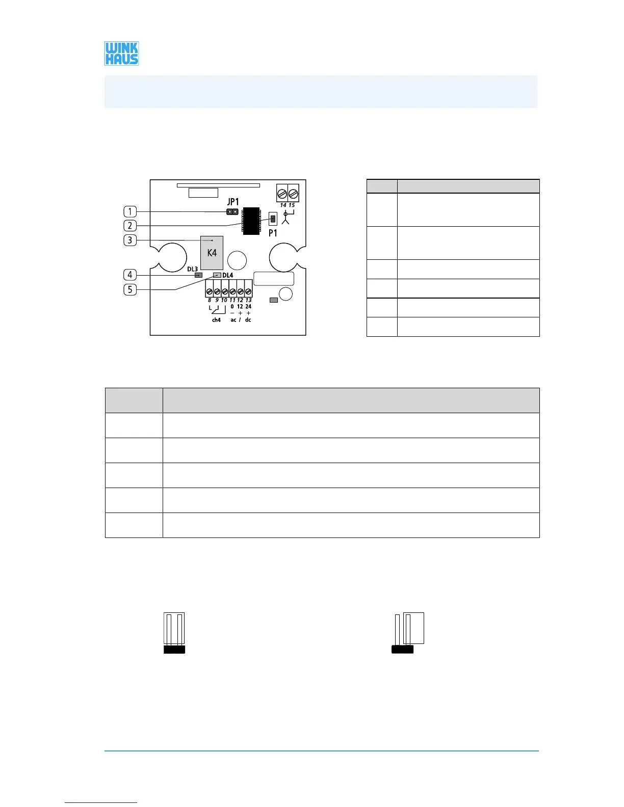
No. Terminals
8, 9 NO relay K4 - non-operated contact is
open, it closes by activating per hand-held
transmitter
9, 10 NC relay K4 - non-operated contact is
close, it opens by activating per hand-held
transmitter
11, 12 “12 V AC/DC”
11, 13 “24 V AC/DC”
14 “Antenna”
15 “Screen”
Figure 3.5.2.-2: Terminal assignment of the circuit board of the receiver
No. Name
[1] “JP1 jumper”
[2] “P1 key”
[3] “K4 relay”
[4] “red LED”
[5] “green LED”
• You can set the K4 relay as ON/OFF or as an impulse via the JP1 jumper (see figure
3.5.2-3). The setting depends on the control unit which is to be triggered by the
receiver.
• Relay becomes briefly active after being
activated per hand-held transmitter and
after about 1 sec. it will be deactivated
automatically.
• Relay remains active after being activated
per hand-held transmitter.
• Deactivation by actuating the hand-held
transmitter once more.
Figure 3.5.2-3: Setting the K4 relay
JP1 = ON
K4 ON/OFF
JP1 = OFF
K4 Impuls
3. Installation
 Loading...