Page 20
Winkhaus STV
Operating Manual EAV 0124653 0505
Subject to technical changes
Winkhaus STV GmbH & Co. KG · Berkeser Str. 6 · D-98617 Meiningen · Germany · www.winkhaus.de · stv@winkhaus.de
3.5. Access control system, wireless remote control
Prerequisites for installation:
• To ensure the reliable performance, the position of the wireless receiver is of utmost
importance for the received power.
• Do not install it at or nearby sources of possible interference (e.g. EDP/high-perfor-
mance power distributor)
• To prevent manipulations to the receiver we recommend installing the receiver on
the inner side of the door!
3.5.1. Wireless remote control set
Installation sequence:
• Install the wireless receiver in a standard flush-type box on the inside.
NOTICE!
If you use the flush-type box of the button, the box will have to be 65 mm
[2.559“] deep!
• Unless you use a switch or button beside the door; you will have to provide a flush-
type box with a filler panel for the wireless receiver.
DANGER!
For safety reasons, you are not permitted to install it in a
flush-type box with a 230 V switch or socket outlet!
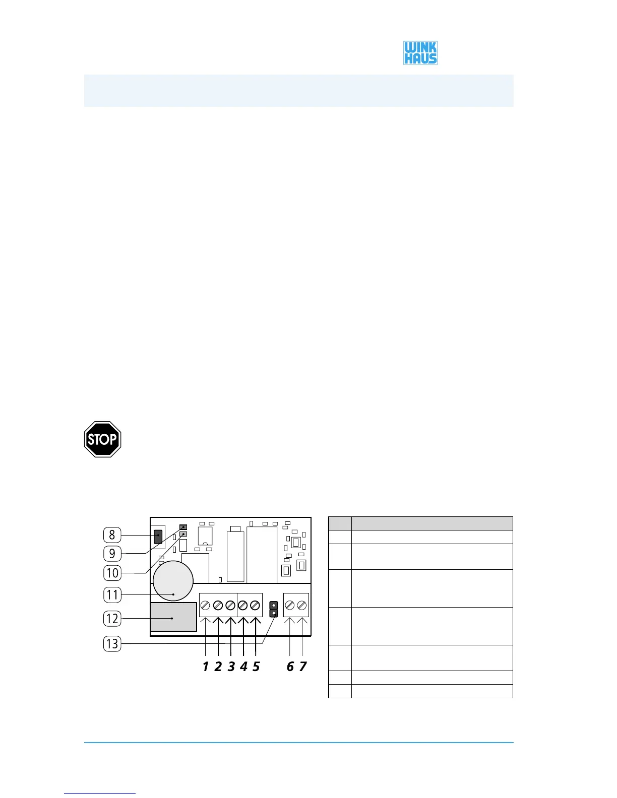
• Connect the terminals 2 through 5 of the wireless receiver as described in the table
below.
No. Terminals
1 “Break contact (NC)”, is not required
2 connect “Contact (C)” - to the green wire at the
cable transition
3 connect “Make contact (NO)” - to terminal 4 of the
wireless receiver
(+ 12V DC)
4 connect “12 V DC or 24 V DC” - with the white wire
of the cable transition
+ terminal 2 of the wireless receiver
5 Connect “0 V DC” - with the brown wire of the
cable transition
6 “Auxiliary antenna/ANT” (not required)
7 “Auxiliary antenna/GND” (not required
Figure 3.5.1-1: Terminal assignment of the wireless receiver
3. Installation
 Loading...