Shadow VI User Manual 1107200
Installation and Checkout Chapter 2 page 37
must be mounted in line with each other so each phototransistor in the receiver can detect the
light beam coming from its opposite light emitter. The Laser Alignment Tool (illustrated in
Figure 2-6 and Figure 2-7) is a useful tool when installing mirrors.
.19
(.48)
1.75
(4.45)
1
(2.54)
.75 (1.91)
See table
50°
MAX
1
(2.54)
Top view
3.89
(9.88)
2.25
(5.72)
4.62 (11.73)
3.75 (9.53)
3.25 (8.26)
2
(5.08)
A B C D
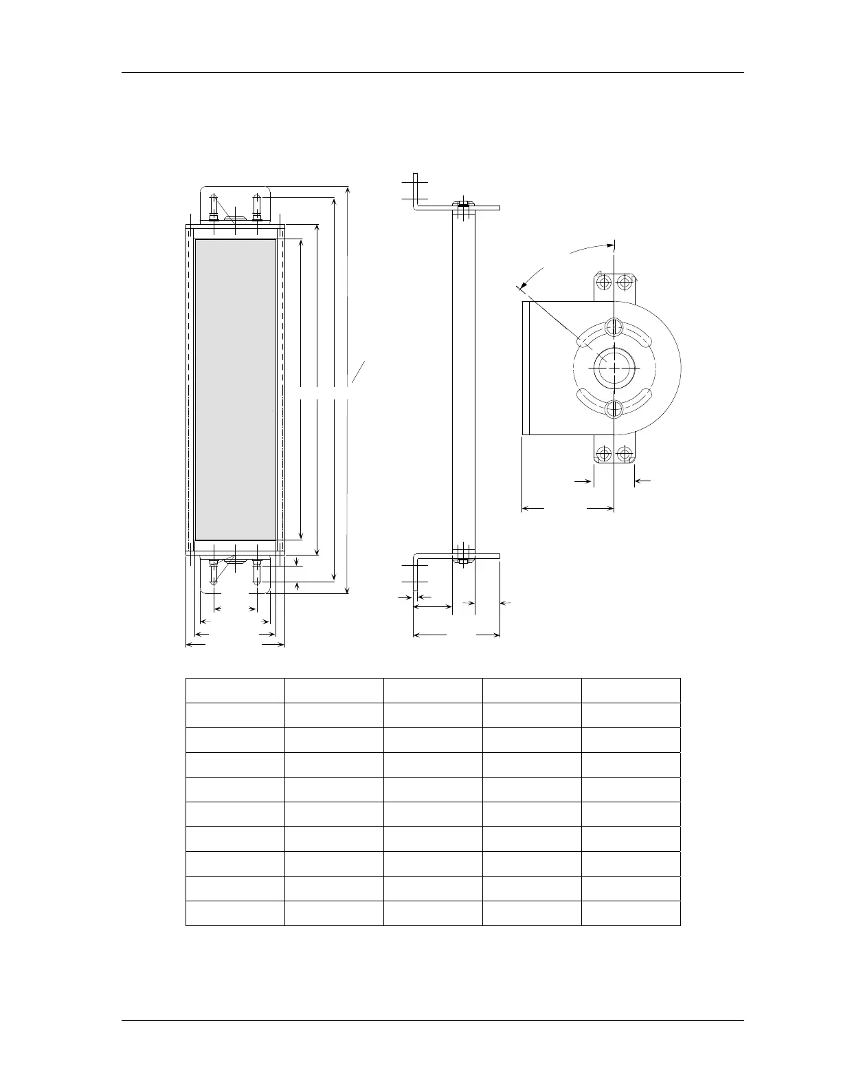
Model A B C D
6” 8 9.38 11.88 12.64
12” 14 15.38 17.88 18.64
18” 20 21.38 23.88 24.64
24” 26 27.38 29.88 30.64
30” 32 33.38 35.88 36.64
36” 38 39.38 41.88 42.64
42” 44 45.38 47.88 48.64
48” 50 51.38 53.88 54.64
60” 62 63.38 65.88 66.64
Figure 2-9. Shadow VI Mirror Dimensions


 To Next Page