Shadow VI User Manual 1107200
Installation and Checkout Chapter 2 page 59
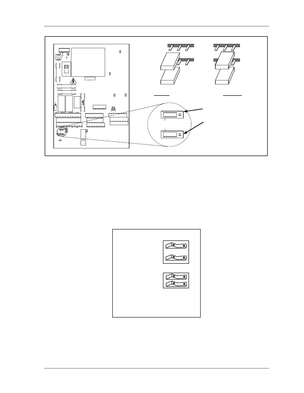
Set MPCE2 at JP15
Set MPCE1 at JP14
TB2
1
1
TB1
TB4
FSD1 FSD2 STAT
MPCE1 MPCE2 RESET XMTR INT
J15
J14
INT
DS8
GND
DS6
ON OFF
PWR UP
RESET
DISABLE
RESET ON
INTERRUPT
S4
S1
FLOATING
WINDO W
STAT=GRN
OPTIONS
TRANSMITTER 2
VCR VCC GN D SHUTDOWN SYN C SHI ELD
VCR VCC GNDSHUTDOWN SYNCSHIELD
TRANSMITTER 1
TB3
1
FWIN VCC GND 2A SYNC SHIE LD2B
FWIN VCC GND 1A SYNC SHIELD1B
RECEIVER 2
RECEIVER 1
1 SET
J12
DS5
TB5
1
GRN AMB RED YEL V-OUT
J13
F2
F3
K1 K2
F1
S2
115 V
DS1
DS2
K3
F4
DS3
DS4
J11
Note:
Factory setting is “Internal” (INT).
For “Internal” place jumper
on
left-hand two pins.
For “External” place
jumper on right-hand two pins.
J15
J14
INT
J15
J14
INT
J15
J14
INT
Figure 2-22. Setting MPCE Jumpers
Making Settings Inside the Control
Follow these steps to make the proper switch settings inside the control. Refer to the location
of components found at Figure 2-14. Also look at the illustrations that follow, which show
the factory settings for the switch blocks S1 and S4 and jumper block J12.
factory settings: OFF
S1
floating window
status relay follows
stop outputs
ON OFF
S4
power up
reset disable
reset on
interrupt
ON OFF
Figure 2-23. Factory Settings for Switch Blocks S1 and S4