Operating Manual V-Drive
+
/V-Drive economy
Page en-10
Index: 11 2022 D005924 Release: 30.04.2019
6 Mounting, Putting into Operation
Please observe the instructions in the “General Safety Instructions” in
section 3.3.1.
6.1 Preparation
All gearboxes are treated with an anti-corrosion agent at the gear input and output.
Remove all traces of the anti-corrosion agent in all versions before mounting the
gearbox.
Attention
Pressurised air can damage the gearbox seals, and thus lead to leakage.
Do not blow out the flanges with pressurised air when cleaning.
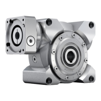
Fig. 6.1
In the gear unit housing are four threaded bores on each of
three surfaces (fig. 6.1).
Use all threaded bores of one surface to secure the
gearbox to your machine.
Threaded bores in the gear unit housing
Gearbox
size
Bolt size Thread depth
[mm]
Property
class
Tightening
torque [Nm]
040 M 6 11.0 8.8 9
050 M 8 13.5 8.8 24
063 M 10 17.0 8.8 48
080 M 12 19.5 8.8 83
100 M 12 19.5 8.8 83
Table 6.1
6.2 Mounting the Motor
6.2.1 General Information
If the gearbox is not delivered with an attached motor, it is to be motor-mounted.
The motor to be mounted must:
• correspond to the B5 design,
• have a radial and axial runout tolerance of “N” according to DIN 42955 and
• if possible, have a smooth shaft.
Attention
Distortion can damage the motor and the gearbox.
Ensure that the motor is mounted in a vertical position.
6.2.2 Tools for tightening the clamping hub
The clamping bolts M5 to M8 can be tightened through the mounting bores of the adapter
plate using a square ¼ inch socket spanner.
The M10 clamping bolt requires a square ⅜ inch socket spanner, the M12 clamping bolts
require a ½ inch socket spanner. In addition, calibrated torque wrenches are needed
for the respective torque range.
 Loading...