V-Drive
+
/V-Drive economy Operating Manual
Page en-13
Release: 30.04.2019 2022 D005924 Index: 11
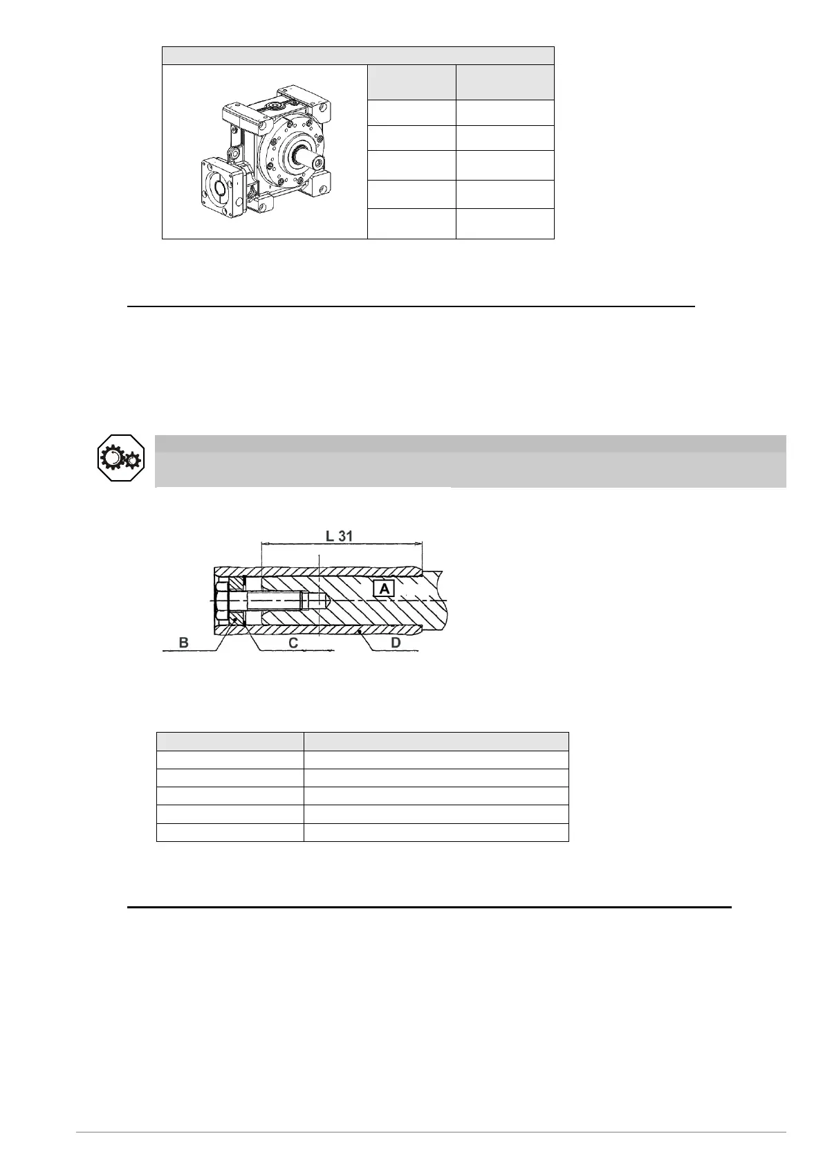
Output shaft
Gearbox
size
F
amax
[N]
040 6500
050 10750
063 18500
080 31250
100 49750
Table 6.4
6.3.3 Assembly on the hollow shaft with shaft key (version VDH
+
/VDHe with groove)
The shaft end of the machine must be equipped with a DIN 6885 Part 1, Form A shaft key
and must have a DIN 332 Form DS centering (with thread).
∇ Check the hollow and load shafts for damaged edges or poor fit. Re-machine the parts if
necessary and clean them.
Protect the cleaned contact surfaces against rust with a suitable lubricant (e.g. Klüger
Altemp Q paste).
Attention
Incorrectly aligned shafts can lead to damage.
Ensure that the hollow shaft is aligned with the load shaft.
Fig. 6.4
The axial securing of the hollow shaft
gearbox to the load shaft (A) can be made
with an end washer (B) and a retaining
ring (C).
If the end washer is to be used for
dismantling as a forcing washer, the load
shaft (A) may not exceed a certain insertion
length (L 31) in the hollow shaft (D). The
maximum insertion lengths are specified in
the following table.
Gearbox size Maximum insertion length L 31 [mm]
040 64
050 77
063 89
080 119
100 159
Table 6.5
6.3.4 Mounting on the hollow output shaft with shrink disk (version VDH
+
/VDHe smooth)
The hollow shaft is axially secured to the load shaft by means of a shrink disk connection.
The shrinkable disk is delivered ready to be installed.
If a different shrink disk is used, observe the instructions of the manufacturer.
The material of the shrink disk is specified in the article code (AC) (see Table 6.7).


 To Next Page