V-Drive
+
/V-Drive economy Operating Manual
Page en-5
Release: 30.04.2019 2022 D005924 Index: 11
3.5.3 Additional Information
Environment
Prevent the penetration of the lubricant into drains, sewers, and water resources.
You can receive further information on the lubricants directly from the manufacturer:
Standard lubricant
OPTIGEAR SYNTHETIC 800/220
(formerly TRIBOL)
Lubricants for the food industry
(NSF-H1 registered)
Castrol Industrie GmbH, Mönchengladbach
Tel.: +49 2161 909-30
www.castrol.com
Klüber Lubrication München KG,
München
Tel.: 49 89 7876-0
www.klüber.com
Table 3.1
4 Technical Specifications
4.1 Design
The gearboxes are comprised of low-backlash angle gears.
All gearboxes are factory-filled with oil; gear input and output sides are sealed with radial
shaft sealings.
The clamping hubs enable a quick and easy mounting of the motor:
The motor is centred on the gearbox axle using the bearing-supported clamping hub
and not the adapter plate. The motor can thus be mounted without radial distortion.
High flexibility is assured by being able to adapt the reducer to various motors through the
functions of adapter plate and the spacer sleeve.
The gearbox has been designed to compensate for thermal linear expansion of the motor
shaft.
For varying applications, the gearbox is available with:
• Output flange “VDT
+
”,
• Output shaft “VDS
+
/VDSe” and
• Hollow output shaft “VDH
+
/VDHe”.
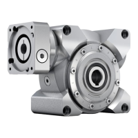
4.1.1 “VDT
+
” with output flange
Fig 4.1
The output flange, in accordance with ISO 9409, has two
centring mechanisms and a bore hole for an indexing pin so
that the gearbox (or the application) can be zeroed
mechanically.
The hollow shaft running through serves as a conduit for lines
or hoses, but does not aid in securing the load. On the back
side of the output flange, the position and/or the speed of the
load can be measured through the hollow shaft.
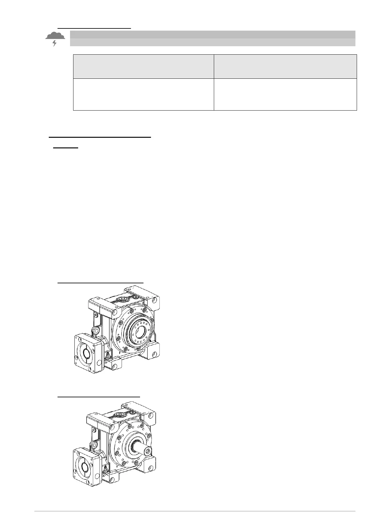
4.1.2 “VDS
+
” with output shaft
Fig 4.2
The output shaft is available in the following forms:
• Smooth face,
• With feather key groove (according to DIN 6885) or
• Involute (according to DIN 5480).