V-Drive
+
/V-Drive economy Operating Manual
Page en-23
Release: 30.04.2019 2022 D005924 Index: 11
11 Appendix
11.1 Tightening torques for common thread sizes in general mechanics
The specified tightening torques s for headless screws and nuts are calculated values and
are based on the following conditions:
• Calculation acc. VDI 2230 (Issue February 2003)
• Friction value for thread and contact surfaces μ =0.10
• Exploration of the yield stress 90 %
Property
class
Tightening torque [Nm] for threads
M 3
M 4
M 5
M 6
M 8
M 10
M 12
M 14
M 16
M 18
M 20
M 22
M 24
8.8 1.15 2.64 5.24 8.99 21.7 42.7 73.5 118 180 258 363 493 625
10.9 1.68 3.88 7.69 13.2 31.9 62.7 108 173 265 368 516 702 890
12.9 1.97 4.55 9 15.4 37.3 73.4 126 203 310 431 604 821 1042
Table 11.1
11.2 Setting the torsional flank backlash
Inspection
The gearbox is set by the manufacturer with a minimal torsional flank backlash. The process
of wear, as well as extended operating times, can cause the backlash to increase.
Readjustment
Due to decreasing of the centre distance from worm gear shaft and worm wheel,
the torsional flank backlash can be reduced.
If necessary, dismantle the gearbox from the entire machine as described
in section 9.
Attention
If you remove the side cover of the gearbox, oil loss will result.
When performing adjustments, leave the cover in place.
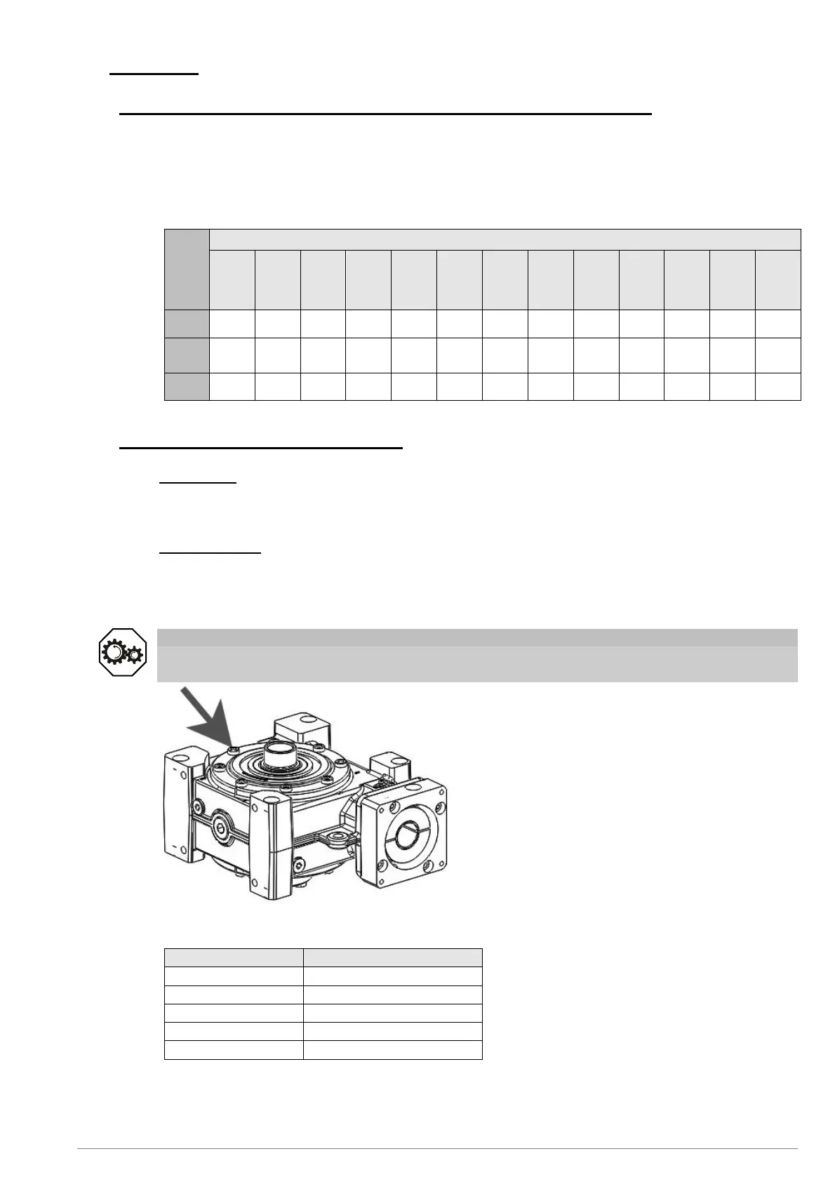
Fig. 11.1
Remove the inner hexagonal bolts on both
side covers (see fig. 11.1).
On the covers are markings pointing to the
numbers on the housing.
Turn the covers so that the marking points
to the next highest number. Both covers
must point to the same number.
∇ Check whether the toothing has enough
backlash by turning the worm gear
several times.
Reinsert the inner hexagonal bolts
in the cover.
The table below specifies the prescribed tightening torque.
Gearbox size Tightening torque [Nm]
040 5
050 7
063 17
080 17
100 34
Table 11.2
∇ Check again whether the gear teeth still have adequate backlash.