V-Drive
+
/V-Drive economy Operating Manual
Page en-11
Release: 30.04.2019 2022 D005924 Index: 11
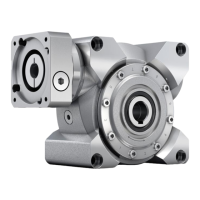
6.2.3 Assembly
Smooth shaft with spacer sleeve Grooved shaft with spacer sleeve
Fig. 6.2
If the motor shaft has a feather key, remove the feather key.
A clamping hub connects the motor shaft and the gear drive shaft. A slotted spacer sleeve is
additionally used for certain motor shaft diameters and applications (fig. 6.2).
Clean the plane fitting surfaces of the motor and gearbox.
Clean/de-grease the motor shaft, the clamping hub bore hole and, if required, the spacer
sleeve.
∇ Take care that the slot of the spacer sleeve is positioned coincident to the slot of the
clamping hub.
Turn the clamping hub so that the clamping screws are positioned coincident to the
mounting holes in the adapter plate.
Attention
Excessively high axial forces can damage the motor and gearbox.
Ensure that the axial forces that occur are not higher than the values specified
in Table 6.2.
Gearbox
size
Clamping hub
interior Ø
[mm]
Clamping screw
DIN EN ISO
4762-10.9
Width across
flats
[mm]
Tightening
torque
[Nm]
Max. axial
force
[N]
040
≤ 14
M 5 4 8.5 42.5
050
≤ 19
M 6 5 14 51
063
≤ 28
M 8 6 30 49
080
≤ 35
M 10 8 65 80
100
≤ 48
M 12 10 115 118
Table 6.2
Attention
Motors with
• shaft shoulder,
• distinctive chamfer radius, or
• longer shafts than are permitted for the relevant gearbox
lead to distortions in mounting, which damage the motor and the gearbox.
Check the interfering edges by measuring, or by a measurement check based on our
catalogue specifications and the information of the motor manufacturer.
Please consult our Customer Service Department to obtain a wider adapter plate or an
intermediary flange.
 Loading...