Operating Manual V-Drive
+
/V-Drive economy
Page en-14
Index: 11 2022 D005924 Release: 30.04.2019
Depending on the material of the shrink disk, the load shaft has to meet the following
conditions:
Material of the shrink disk
Standard Nickel-
plated
Stainless steel
Minimum yield stress [N/mm²]
≥
385 ≥ 260 ≥ 260
Surface roughness Rz [μm]
≤ 16
Tolerance
h6
Table 6.6
Attention
Dirt can inhibit transmission of the torque.
Do not disassemble the shrink disk prior to installation.
De-grease the load shaft and the hollow output shaft's bore leaving no residual traces in
the area of the shrink disk seat.
Only the exterior surface of the hollow output shaft may be greased in the area of the
shrink disk seat.
Attention
The forces of the shrink disk can deform the hollow output shaft.
Always install the load shaft first before tightening the clamping screws of the shrink disk.
Push the hollow output shaft onto the load shaft by hand.
Attention
Incorrectly aligned shafts can lead to damage.
Ensure that the hollow output shaft is aligned with the load shaft.
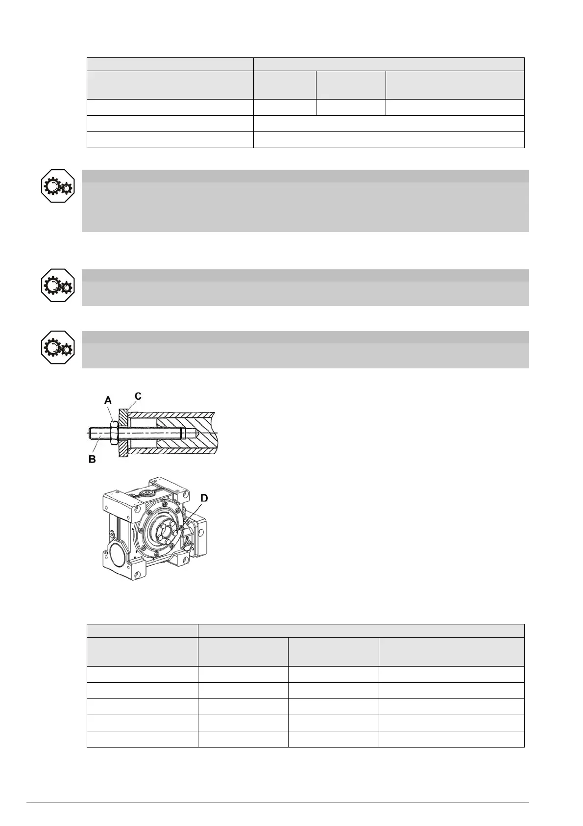
Fig. 6.5
Mount the hollow output shaft onto the load shaft using a
nut (A) and a threaded spindle (B). The supporting (C)
has to be performed by the hollow output shaft.
Fig. 6.6
The article code is located, depending on the design, on the
front side or the circumference of the shrink disk.
Refer to the article code to determine the material of the
shrink disk.
Tighten the clamping screws (D) of the shrink disk evenly
distributed in multiple circular passes.
Tighten the individual clamping screws only up to the
maximum permitted tightening torque.
For screw sizes and specified tightening torques, see
Table 6.7.
Material of the shrink disk: Standard
Gearbox size
V-drive
Article code
(AC)
Tightening
torque
Clamping screw thread
040
20001389 12 Nm M6
050
20020687 13 Nm M6
063
20020688 30 Nm M8
080
20020689 34 Nm M8
100
20020690 34 Nm M10
 Loading...