3064812_201804 9
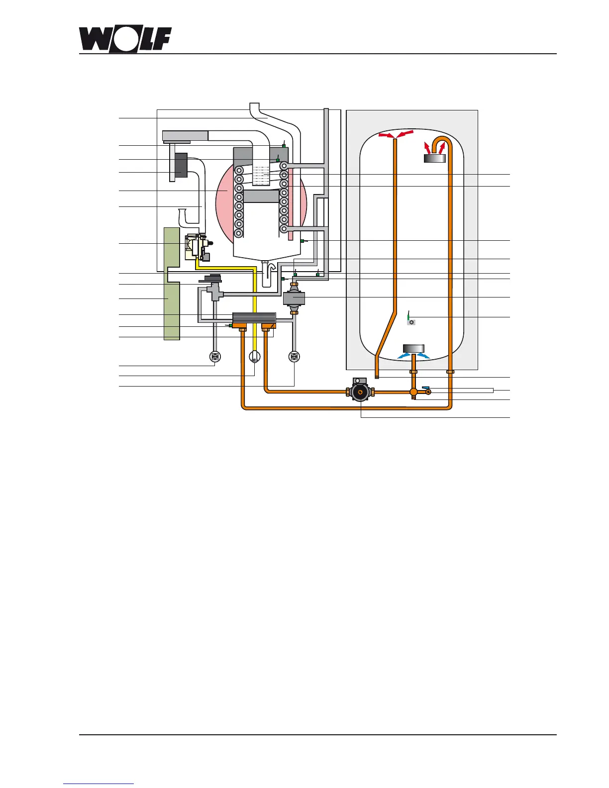
5. CGW-2appliancedescription
CGW-2
Gascondensingcentre
4
2
1
3
19
17
18
20
21
22
24
26
25
27
28
23
5
6
7
9
8
10
13
11
12
14
15
16
1 Flue pipe
2 Combustion chamber cover HLSC (thermostat)
3 Combustion chamber temperature sensor
(eHLSC sensor)
4 Gas fan
5 Expansion vessel
6 Mixing valve
7 Gas valve
8 Trap
9 3-way valve
10 Control unit enclosure
(GBC-e burner control unit, top)
(HCM-2 control unit PCB, bottom)
11 Plate heat exchanger
12 DHW outlet temperature sensor
13 Non-return valve
14 Heating ow (accessory)
15 Gas supply pipe
16 Heating return (accessory)
17 Burner
18 Heating water heat exchanger
19 Flue gas temperature sensor
20 Pressure sensor
21 Return temperature sensor
22 Boiler water temperature sensor
23 Heating circuit pump with air vent valve
24 Cylinder temperature sensor
25 DHW connection
26 BDF valve/DHW circulation connection
27 Cold water connection
28 Cylinder primary pump