Setup
Side cutter setup
Setup doc050624 3-24
3
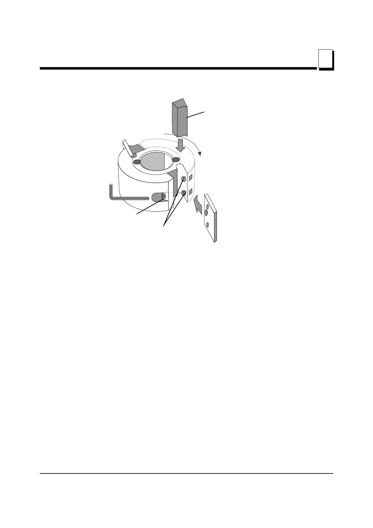
See Figure 3-18.
Ensure that the chip deflector in front of the movable cutter does not get bent by the
unplaned edge of the work piece coming in contact with the cutter. Be cautious process-
ing work pieces of various widths.
Ensure that the cutter head can rotate freely, and that there is approximately 5 mm (0.2”)
between the outermost cutting diameter of the cutter and the chip deflector that works as
a chip barrier behind the movable cutter.
SETTING SIDE CUTTER KNIFE HEIGHT
Included with your planer is a package of shims/spacers of various thicknesses for the
side cutter heads. These shims are packed in the parts box that is packed with your
planer.
FIG. 3-18
Lock screw
Gib
Dowel pins
Rotation direction
 Loading...