Dealer Service 23
MAN1246 (04/10/2018)
CROSSBAR REMOVAL
1. It is necessary to gain access to bottom side of cutter for crossbar
removal. See Blocking Method page 13.
NOTE: You will need to use either the puller screw (Item 6, Figure 15) or
a small hydraulic jack to remove the crossbar.
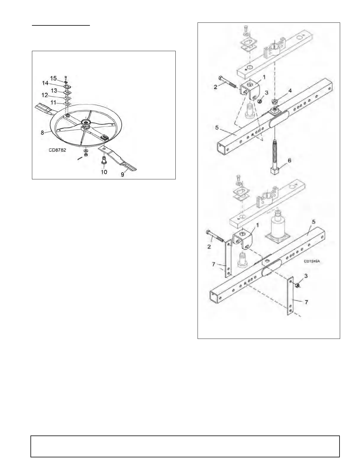
2. Remove blades from crossbar as shown in Figure 14.
Figure 14. Blade Removal
3. Refer to Figure 15. Remove cotter pin from bottom of crossbar and
remove nut and washer.
4. Attach a clevis (1) to each end of crossbar, using blade pins, spacers,
keyhole plates, and blade pin clips.
5. Position tube assembly (5) with threaded nut (4) toward crossbar for
puller screw removal or down for hydraulic jack removal.
6. For removal with puller screw, attach tube (5) to each clevis with bolts (2)
and nuts (3). Place pad (4) in nut and thread puller screw (6) into nut from
bottom. Tighten until pad is solid against gearbox shaft. For best results,
strike head of puller screw with a hammer while tightening with a wrench.
7. For removal with a jack, attach tube to each clevis with puller links (7),
bolts (2), and nuts (3). Place jack on tube with end of jack pressing
against gearbox shaft. Slowly apply force with jack.
NOTE: Hydraulic jack will not operate if tipped more than 90°. Use care
to prevent bending crossbar during removal.
Figure 15. Crossbar Removal
8. CROSSBAR ASSEMBLY
9. BLADE
10. 38.1mm (1-1/2) BLADE PIN
11. SHIM 1.2 mm (18 GA)
12. SHIM .9 mm (20 GA)
13. 7.9mm (5/16) SPACER
14. KEYHOLE PLATE
15. BLADE IN LOCK CLIP
16. 1/2 NC X 1-1/4 HHCS GR5
1. Crossbar puller clevis
2. 5/8 NC x 4-1/2 HHCS
3. 5/8 NC Hex nut
4. Crossbar puller pad
5. Crossbar puller tube
6. Crossbar puller screw
7. Crossbar puller link
 Loading...