18 Owner Service
MAN1298
(
08/01/2023
)
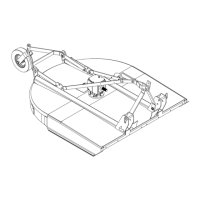
Figure 10. Jackstand Placement and Lubrication Points
BLADE SERVICING
Blade Removal
(Figure 11)
■ When sharpening blades, grind the same
amount on each blade to maintain balance.
Replace blades in pairs. Unbalanced blades will
cause excessive vibration, which can damage
gearbox bearings. Vibration may also cause
structural cracks to cutter.
■ If blade pin (7) is seized in crossbar and extreme
force will be needed to remove it, support cross-
bar from below to prevent gearbox damage.
1. Disconnect driveline from tractor PTO.
2. Raise cutter and block securely (see Blocking
Method, Figure 10).
3. Align crossbar (1) with blade access hole in the
cutter frame. Remove blade pin nut (5) and lock
washer (4). Carefully drive pin (3) out of crossbar.
4. Rotate crossbar and repeat for opposite blade.
Figure 11. Blade Assembly
Blade Installation
(Figure 11)
■ Your dealer can supply genuine replacement
blades. Substitute blades may not meet orig-
inal equipment specications and may be
dangerous.
■ Crossbar rotation is counterclockwise when
looking down on cutter. Be sure to install
blade cutting edge to lead in counterclockwise
rotation.
1. Inspect blade pin (3) for nicks or gouges, and if you
nd any, replace the blade pin.
NOTICE
CAUTION
1
2
3
4
5
6
7
7
X
X
X
X
CD8134
X = JACKSTAND PLACEMENT
1. Front U-joint ........................8 hrs
2. Slip joint (apply grease
to inner shaft) ...................... 8 hrs
3. Rear U-joint .........................8 hrs
4. Gearbox ..............................Daily
5. Tailwheel pivot tube ............8 hrs
6. Tailwheel ............................. 8 hrs
7. Plastic shield bearings ........8 hrs
1
2
3
4
5
CD8111
1. Crossbar
2. Blade
3. Blade pin
4. Lock washer
5. 1-1/8 NF Jam nut
 Loading...