Assembly 29
MAN1298
(
08/01/2023
)
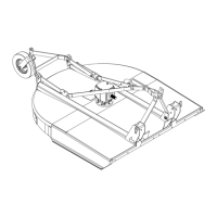
Figure 28. Cutter Assembly
DISASSEMBLE SHIPPING UNIT
(Figure 27)
Remove wood blocks from front and bottom of cutter.
Remove all parts that are zip tied or wired to cutter.
Remove cap screws and ange lock nuts that are se-
curing Lift Arms (4) and Break Links (3) to cutter.
Remove cap screws and ange lock nuts that are se-
curing Tailwheel Bracket (9) to cutter.
Remove Upper Mounting Hardware (2) from A-Frame
Bars (1).
ASSEMBLE CUTTER
(Figure 28)
1. Attach Tailwheel Bracket (9) and Lift Arms (4) to cut-
ter rail using 1/2 NC x 2 cap screws (17) and 1/2 NC
ange lock nuts (19).
2. Select desired height adjustment holes and secure
Tailwheel Bracket (9) with 1/2 NC x 1-1/2 cap screws
(18) and 1/2 NC ange lock nuts (19).
3. Rotate A-Frame Bars (1) up and attach Break Links
(3), Sleeve (2) to lower hole in top of A- Frame Bars
(1) using 3/4 NC x 5-1/2 cap screw (13) and 3/4 NC
lock nut (14).
4. Rotate Lift Arms (4) upward and attach to Break
Links (3) using Sleeves (5), 5/8 NC x 2-1/2 cap
screws (15), and 5/8 NC ange lock nuts (16). See
Attaching Cutter to Tractor, pg. 12 for adjustments.
5. Attach Rubber Belting (8) and Belting Bar (10) to
front of cutter using 3/8 NC x 1-1/4 carriage bolts
(11) and 3/8 NC ange lock nuts (12). (Omit if in-
stalling optional chain shielding).
6. Secure Tailwheel (7) to Tailwheel Bracket (9) using
33 mm washer (6) and spirol pin (20).
1
2
3
4
4
5
6
7
8
9
10
11
12
13
14
15
16
17
18
19
20
CD8121
1. A-Frame bar
2. .75 x 1.25 x 3.0 Sleeve
3. Break link
4. Lift arm
5. .626 x 1.00 x 1.26 Sleeve
6. .33 mm Flat washer
7. Tailwheel
8. Rubber belting
9. Tailwheel bracket
10. Belting bar
11. 3/8 NC x 1-1/4 Carriage bolt
12. 3/8 NC Flange lock nut
13. 3/4 NC x 5-1/2 Cap screw
14. 3/4 NC Lock nut
15. 5/8 NC x 2-1/2 Cap screw
16. 5/8 NC Flange lock nut
17. 1/2 NC x 2 Cap screw
18. 1/2 NC x 1-1/2 Cap screw
19. 1/2 NC Flange lock nut
20. Spirol pin

 Loading...