723PLUS/Analog Load Sharing Manual 02879
130 Woodward
Discrete Input Module
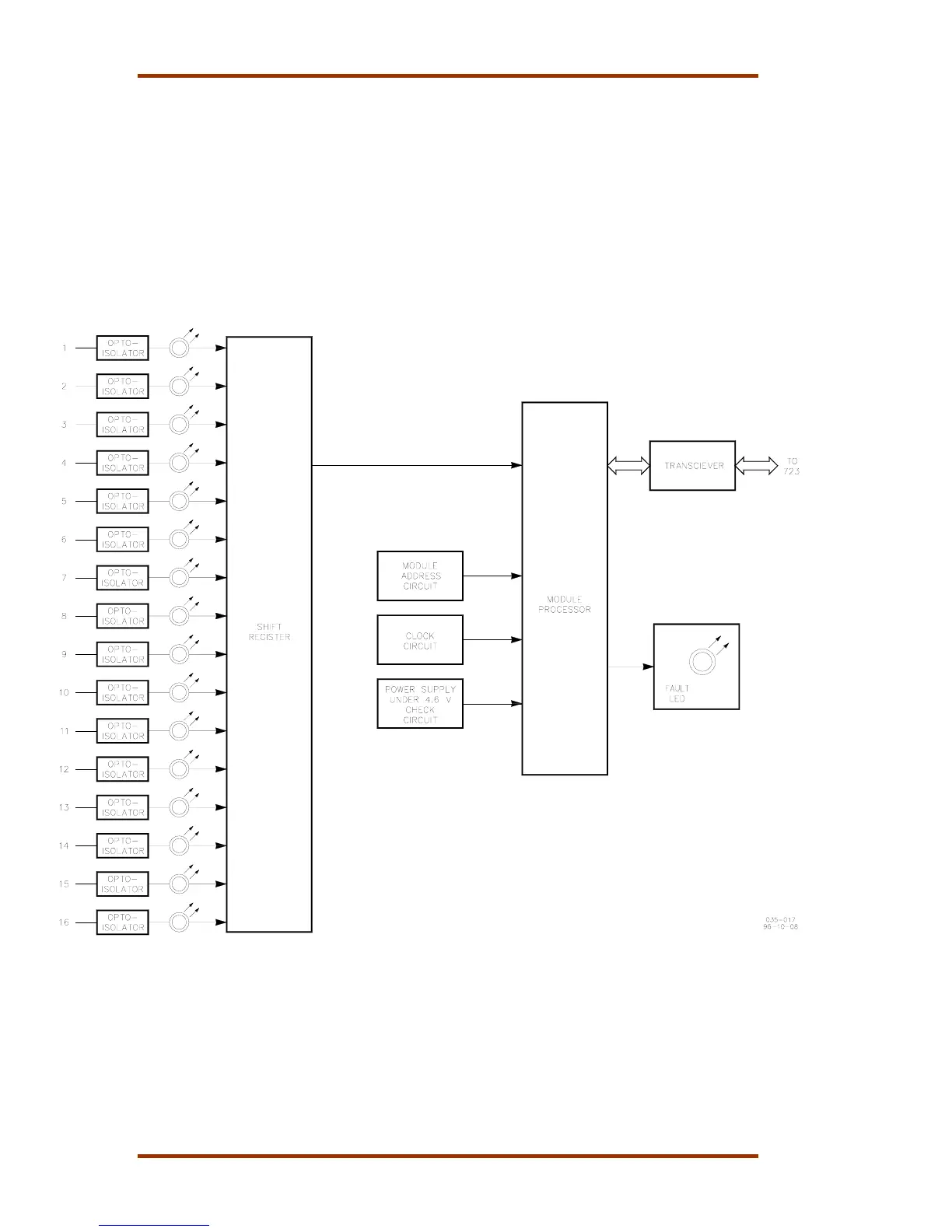
Figure B-3 is a block diagram and Figure B-4 is a wiring diagram of the Discrete
Input module. The module receives information from field switches and relays.
Power is provided for these contacts, on four terminal blocks, TB-5 through TB-8.
The input power on TB-2 may also be used, but does not have the benefit of an
internal fuse and some filtering, therefore external fusing should be provided.
The state of each discrete input is passed through an optoisolator and an LED to
the shift register. In this manner, the LEDs will light when a contact is closed. The
module processor receives this information and transmits it through the
transceiver to the 723PLUS.
Figure B-3. Discrete Input Module Block Diagram

 Loading...


