Installation and commissioning
5
Comfort+ II RF – 6720892636 (2019/04)
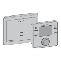
2.2 Key
The Key is used together with the control unit.
The Key is installed in the heat source.
Fig. 2 Key
[1] Connect the Key
[2] LED on the Key
3 Installation and commissioning
CAUTION:
Electrical work
Electrical work must only be carried out by a qualified
electrician.
▶ Before starting electrical work:
Isolate the mains electrical supply and secure against
unintentional re-connection.
▶ Check for zero voltage.
▶ Also observe connection diagrams of other system
components.
For information on the heat source,
Technical documentation for the heat source.
These instructions contain the installation and operating
instructions for the Comfort+ II RF control unit.
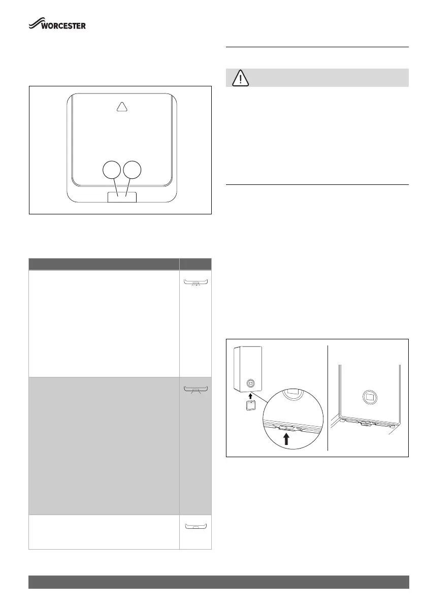
3.1 Installation and commissioning key
Installation in the heat source
▶ Isolate the mains electrical supply and secure against
unintentional reconnection.
▶ Install Key in the heat source. For wall mounted gas boilers,
through insertion into the key slot from below.
For information on the installation in the heat source
technical documentation of the heat source.
Fig. 3 Install Key
Description of the LED displays Example
Red flashing LED:
Fault, e.g. no EMS connection:
▶ Install Key again, reproduce last functional
state.
Yellow flashing:
Pairing-mode, new/additional wireless participant
can be registered.
Flashing green:
No fault, initialisation process is running.
Constant red:
Temporary fault, e.g. no wireless participant
within range:
▶ Wait for normal operating condition to be
resumed.
Constant yellow LED:
No fault, no wireless participant registered/
connected on the key:
▶ Separate control unit and then reconnect
with key ( Chapter 6.6, page 15).
Constant green LED:
No fault, normal operating condition.
LED Off:
No fault, power-saving mode or appliance
switched off.
1 2
0010021545-002
0010022807-002
1. 2.
 Loading...