Installation
35
Greenstar 4000 – 6 720 891 161 (2020/09)
Running pipes behind the appliance.
• Do not cross pipes over one another.
• Consider the routing of the flue pipe prior to fixing the position of
additional pipework.
• Only follow the routing defined on the wall mounting template.
5.1.1 Mounting frame fixing
Existing wall fixings positions may be used if the old boiler
was an i Junior, Si or Greenstar i.
▶ The existing wall fixings can be used only if deemed suitable.
▶ In all cases, the 2 bottom fixings will align with i Junior or Si (2005 to
2015) wall frames. In SimpleSwitch cases it is recommended to fix
the bottom screws and use the wall frame itself as the template for
top fixings.
Alternate position for PRV pipe is available for
SimpleSwitch.
▶ PRV pre-plumbing connector (elbow) can be rotated to the right
(approx.45°) to line up with pre-existing PRV installation pipework of
i Junior, Si or Greenstar i.
If replacing an i Junior or Si (2005 to 2015) then a SimpleSwitch flue
adaptor (7 733 601 245) is available for vertical flues or horizontal side
flue outlets. This accessory enables the use of the existing flue hole. This
is only relevant for 60/100mm flues.
Wall mounting template
▶ The wall mounting template has been sized to allow for the minimum
clearances around the appliance, ( section 4.3.3 "Appliance
clearances").
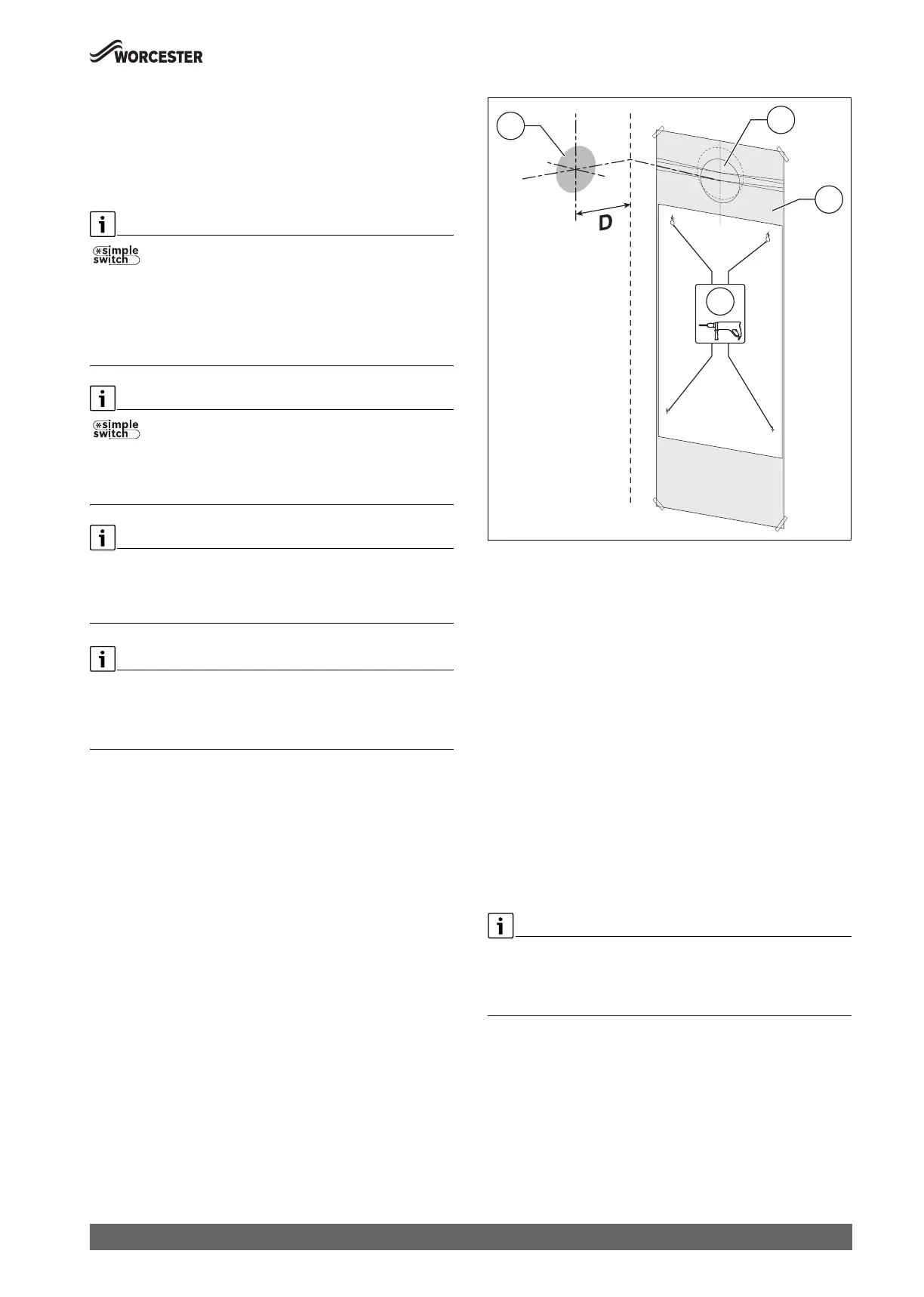
Fig. 43 Wall mounting template
1 Side exit flue example
2 Rear exit flue example
3 Wall mounting template
4 Primary fixing points
D 135mm
The appliance wall mounting template shows the relative positions of the
flue and the top and bottom fixings of the wall mounting frame.
▶ Fix the wall mounting template [3] to the wall in the desired position.
▶ Drill the holes [4] through the template for the primary fixing points
as indicated on the template.
– Additional fixing points for the appliance will be indicated on the
wall mounting template.
– The bottom fixing holes must be used as the plumbing manifold is
not robust enough to support the appliance.
Flue outlet position.
The appliance wall mounting template has the flue centre lines for the
following flue systems:
• 60/100mm
• 80/125mm
Flue turret adaptor
▶ The flue turret adaptor has an in-built 3° angle giving the flue
assembly the rise from the appliance to ensure the condensate flows
back to the appliance.
Rear flue outlet [2].
▶ Mark centre line of flue to be used; the external diameter of the hole
can also be marked if required.
▶ If extensions are to be added then the complete flue must rise at an
angle of 3° from the appliance.
Side flue outlet [1].
▶ Mark from the centre line of the wall mounting template to the wall
which the flue will pass through.
▶ Allow for a rise of 52mm per metre length of flue, to give a 3° angle.
ALL M
UNT
N
TE
ALL M
UNT
N
TE
 Loading...


