Installation
Greenstar 4000 – 6 720 891 161 (2020/09)
36
Example hole size.
• If a 60/100mm diameter flue is to be used, a 125mm diameter hole
is required.
• If using the weather sealing collar by pushing it through from inside
the property, then a 150mm diameter hole is required to
accommodate this.
Flue outlet position marked and ready to drill hole.
▶ Drill hole using a core drill or similar.
▶ Clear any debris from the site.
Appliance fixings and flue outlet drilled and ready.
▶ Remove the wall mounting template.
5.2 Appliance connections
WARNING
Appliance - gas connection
▶ Ensure the mains gas supply is isolated before starting any work
and follow all relevant safety precautions.
NOTICE
Appliance - hydraulic connections
▶ Ensure all water pipework, to be connected, are isolated/drained and
follow all relevant safety precautions.
▶ Be careful of plastic components when using a naked flame on
pipework.
Surplus water may be present inside the appliance due to factory testing.
External condensate pipework or internal pipe runs in unheated areas
such as lofts, basements and garages exposed to prolonged cold
temperatures should be protected ( chapter 4.5).
Plumbing manifold
Further guidance on pipe routing can be found printed on the appliance
template (supplied with the appliance).
For further ease of fitting, an optional Vertical Pre-piping Assembly kit
(7 733 601 250) is available, comprising of pre-formed copper CH and
DHW pipes.
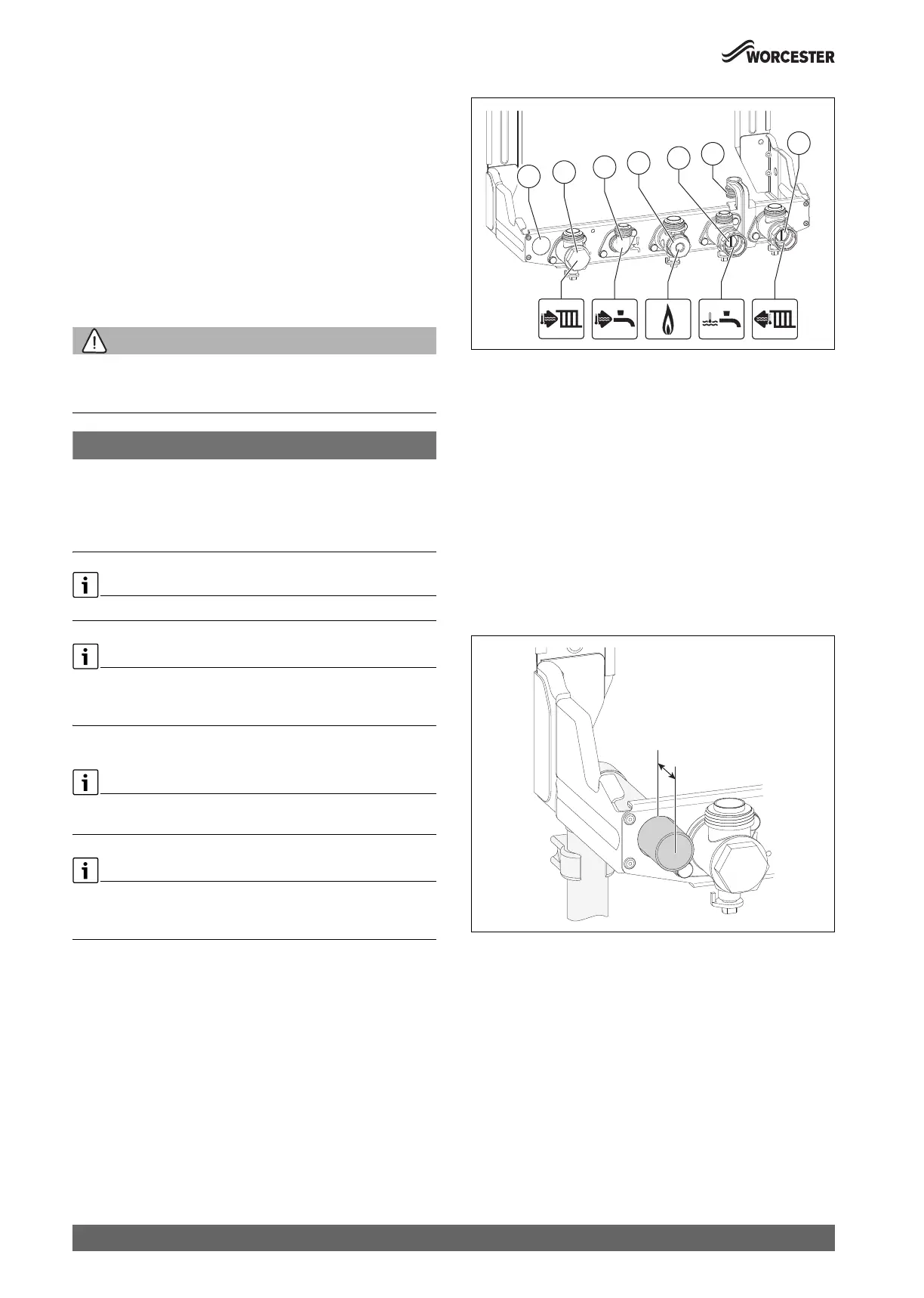
Fig. 44 Connections on the gas and water side
[1] Position for condensate pipe.
[2] CH Flow.
[3] DHW Outlet.
[4] Gas connection.
[5] DCW Inlet.
[6] PRV pre-plumbing connection locator bracket.
[7] CH Return.
Condensate discharge connection preparation
Pre-fit the plastic condensate drain pipe through the wall frame as shown
in figure 45.
▶ Secure the pipe to the wall at the last joint.
▶ Ensure the pipe protrudes through the wall frame by 25mm [D].
▶ If exiting through the wall, to run externally, the pipe must have a 3°
fall and be increased to a 32mm insulated pipe.
Fig. 45 Condensate drain pipework detail
[D] Protrusion dimension - 25mm
 Loading...


