Installation
41
Greenstar 4000 – 6 720 891 161 (2020/09)
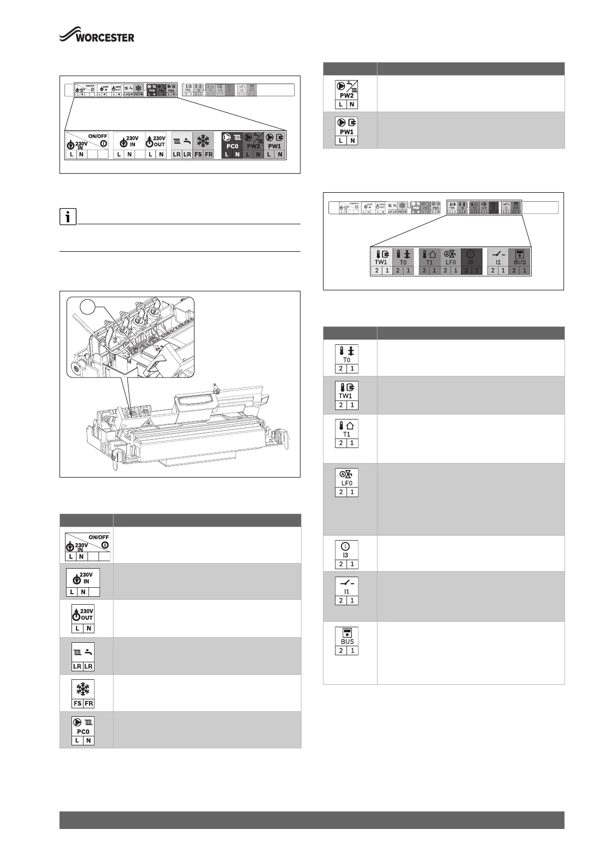
Power supply (power cables) terminal strip
Fig. 57 Power supply (power cables) terminal strip
Earth rail location
Strain relief assembly is removable via a single screw to provide easier
access if required.
Connect the protective conductor (earth) cable from the power lead to
the earth rail [1].
Fig. 58 Earth rail
Power supply (power cables) connections
Table 19 Power supply (power cables) terminal strip for external
accessories
Low voltage (signal cables) terminal strip
Fig. 59 Low voltage (signal cables) terminal strip
Low voltage (signal cables) connections
Table 20 Low voltage (signal cables) terminal strip for optional
accessories
Symbol Function
Power supply (power cable).
Pre-wired cable (Live and Neutral).
No functionality; not used.
230V mains output to external controls/wiring centre.
▶ If required: connect power supply for external
controls.
Switch live (Live Return) to appliance.
• k CH demand input.
• j DHW demand input (pre-heat time control).
External frost thermostat.
• FS output (frost thermostat supply).
• FR input (frost thermostat return).
No functionality; not used.
0010036464-001
1
No functionality; not used.
No functionality; not used.
Symbol Function
No functionality; not used
4000 Combi DHW Pre-heat Kit (accessory)
▶ Connect the 2-core cable supplied with the
accessory.
Outdoor weather compensation sensor (used when
outdoor sensor is connected, optional accessory)
▶ Connect the outside temperature sensor via a 2-
core cable.
Intelligent filling system contact (accessory).
▶ Connect the Intelligent filling system cable
supplied.
▶ Switch on the automatic filling facility in the service
menu under Settings > Special function and
program it according to the heating system.
No functionality; not used
Mechanical control volt-free switching contact.
▶ Remove link and connect the MT20/MT20RF
mechanical controls (accessories).
▶ Connect 2-core cable
Communication BUS connection for hard-wired
Worcester/Bosch EMS controls.
Low voltage power supply for hard-wired Worcester
mechanical controls (MT20/MT20RF).
▶ Connect 2-core cable.
Symbol Function
 Loading...


