Figure 2 Wiring connections diagram
Comms
Temp Sensor
PV+
PV-
Batt+ Batt-
8
7
2
1
4
3
6
5
1 Solar panel 5 Black neg(–) battery cable
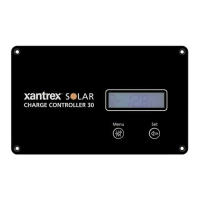
2 Xantrex SOLAR 30A PWM Charge
Controller
6 BTS cable
3 Red pos(+) PV cable.Install a PV
disconnect device.
7 Red pos(+) battery cablewith built
in DC fuse
4
Black neg(–) PV cable
8 12/24V Battery
2. Connect the cables in the following sequence: Battery cables, PV
cables, ground, and accessories, if applicable.
975-1012-01-01 Rev B
Oct 2019
21
 Loading...