Platform Cable USB II
DS593 (v1.2.1) March 17, 2011 www.xilinx.com
30
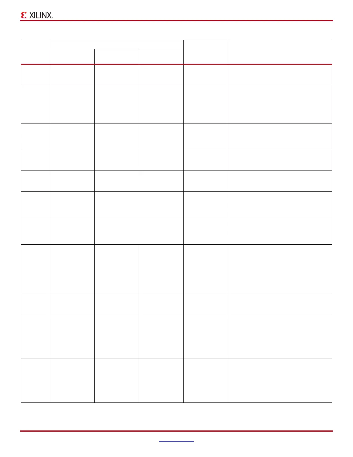
10 TDI – – Out
JTAG Test Data In. This pin outputs the
serial data stream transmitted to the TDI pin
on the first device in a JTAG chain.
13 PGND – – Out
JTAG Pseudo Ground. Use of this pin is
optional. PGND is pulled Low during JTAG
operations; otherwise, it is high-Z. This pin is
connected to an open-drain driver and
requires a pull-up resistor on the target
system.
(4)
14 HALT – – Out
JTAG Halt. Use of this pin is optional. Host
applications can customize the behavior of
this signal. See HALT_INIT_WP Signal in
iMPACT, page 22.
4– SS – Out
SPI Select. This pin is the active-Low SPI
chip select signal and should be connected
to the S
(1)
pin on the SPI flash device.
6– SCK – Out
SPI Clock. This pin is the clock signal for
SPI operations and should be connected to
the C
(1)
pin on the SPI flash PROM.
8– MISO – In
SPI Master-Input, Slave-Output. This pin
is the target serial output data stream and
should be connected to the Q
(1)
pin on the
SPI flash device.
10 – MOSI – Out
SPI Master-Output Slave-Input. This pin
outputs the target serial input data stream
for SPI operations and should be connected
to the D
(1)
pin on the SPI flash device.
13 – PGND – Out
SPI Pseudo Ground. PGND is pulled Low
during SPI operations; otherwise, it is high-
Z. When connected to PROG_B on an
FPGA, the FPGA will high-Z its SPI signals
while the cable is programming the SPI
flash. This pin is connected to an open-drain
driver and requires a pull-up resistor on the
target system.
(4)
14 – WP – –
SPI Write Protect. This pin is reserved for
future use. Do not connect for SPI
programming.
4– – PROGOut
Slave Serial Configuration Reset. This pin
is used to force a reconfiguration of the
target FPGA(s) and should be connected to
the PROG_B pin of the target FPGA for a
single-device system, or to the PROG_B pin
of all FPGAs in parallel in a daisy-chain
configuration.
6 – – CCLK Out
Slave Serial Configuration Clock. FPGAs
load one configuration bit per CCLK cycle in
Slave Serial mode. CCLK should be
connected to the CCLK pin on the target
FPGA for single-device configuration, or to
the CCLK pin of all FPGAs in parallel in a
daisy-chain configuration.
Tabl e 6 : JTAG/SPI/Slave Serial Port: 2-mm Connector Signals (Cont’d)
Pin
Number
MODE
Direction
(2)
Description
JTAG
Configuration
SPI
Programming
(1)
Slave-Serial
Configuration