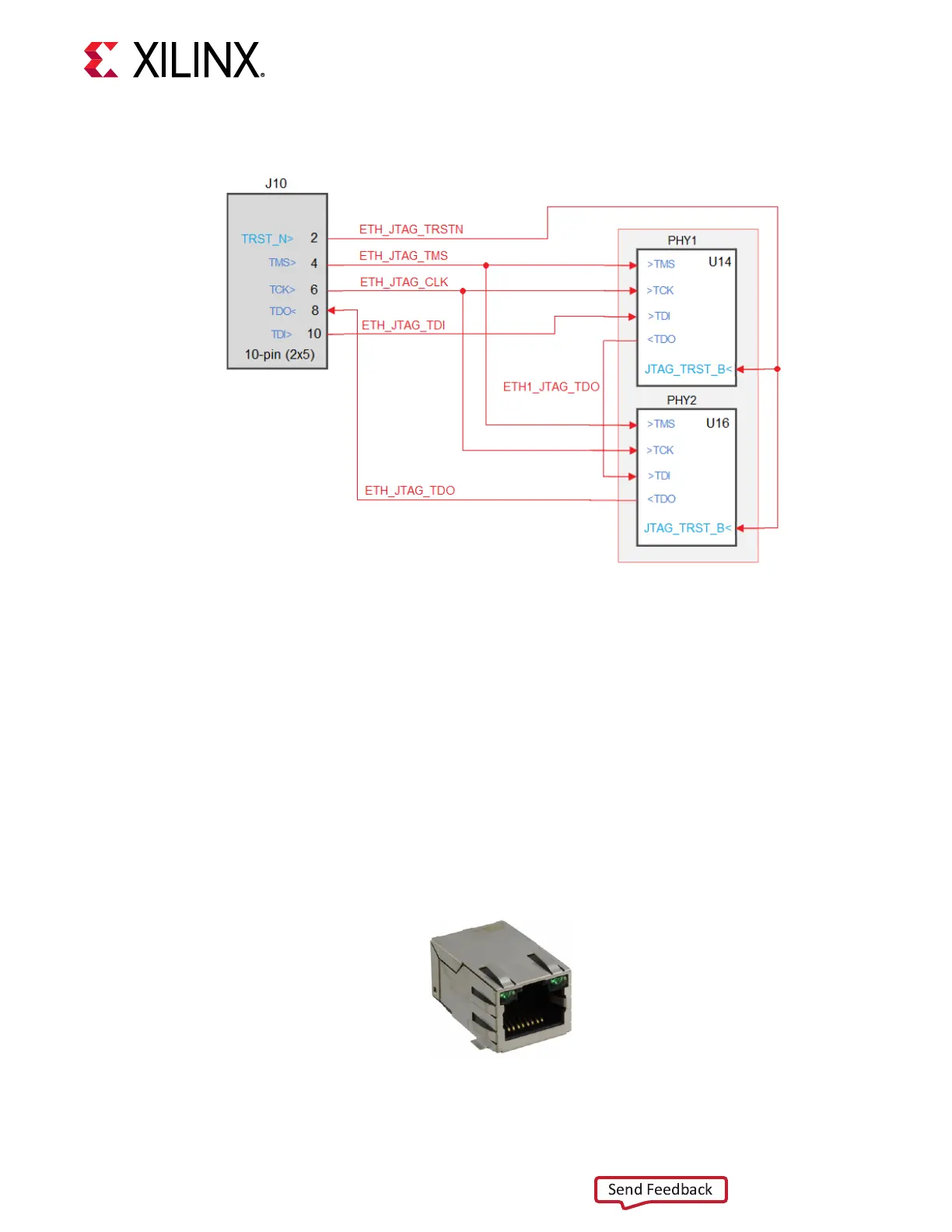
Figure 10: Ethernet JTAG
X22793-042619
The detailed FPGA connecons for the feature described in this secon are documented in the
SP701 board XDC le, referenced in Appendix B: Xilinx Design Constraints.
Ethernet PHY Status LEDs
Figure 2, callouts 8, 9
Each Ethernet PHY is connected to a RJ-45 connector with status LEDs integrated into the metal
frame of the connector. The two PHY status LEDs are visible within the frame of each RJ45
Ethernet jack as shown in the following gure. As viewed from the front opening, the le green
LED is the link acvity indicator and the right green LED is the 1000BASE-T link mode indicator.
Figure 11: Ethernet PHY Status LEDs
Chapter 3: Board Component Descriptions
UG1319 (v1.0) July 12, 2019 www.xilinx.com
SP701 Board User Guide 25