For each Ethernet PHY, a separate discrete LED indicates that a link has been established, as
described in the following list:
• PHY1 DP83867IRPAP U14 RJ-45 J9, link established DS2, near item 25 in Figure 2.
• PHY2 DP83867IRPAP U16 RJ-45 J11, link established D2, near item 9 in Figure 2.
Details about the Tri-Mode Ethernet MAC core are provided in the Tri-Mode Ethernet MAC
LogiCORE IP Product Guide (PG051).
I2C Bus Topology
[Figure 2, callout 17]
The SP701 evaluaon board I2C bus implementaon consists of bus I2C0, shared by the FPGA
U1 HP bank 16 and the MSP430 system controller U25. The I2C bus is routed to a TCA9548A 1-
to-8 bus switch U23 (address 0x74). Seven of the eight bus switch channels are used. The bus
switch can operate at speeds up to 400 kHz.
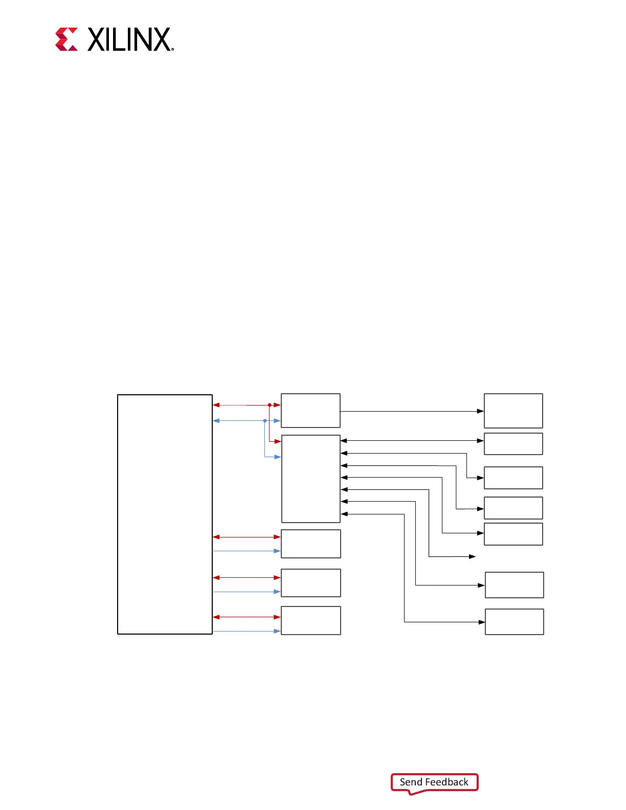
The SP701 evaluaon board I2C bus topology is shown in the following gure.
Figure 12: SP701 I2C Topology
ADV7511
MIPI DSI Conn
Spartan-7
FPGA
MIPI CSI Conn
MSP430
I2C2_SDA
I2C2_SCL
I2C3_SDA
I2C3_SCL
I2C4_SDA
I2C4_SCL
I2C0_SDA
I2C0_SCL
IO Expander
PGOOD Mon
8Ch I2C
Switch
TCA9548APWR
I2C01_SCL/SDA
I2C02_SCL/SDA
I2C03_SCL/SDA
I2C04_SCL/SDA
I2C06_SCL/SDA
I2C05_SCL/SDA
I2C07_SCL/SDA
Test Point for SYS Mon
I2C_MSP430_SDA/SCL
EEPROM
SysCLK OSC
Si570
Power Monitor
(INA226)-12V
Power Monitor
(INA226)-1V
MP5470 PMIC
FMC-LPC
X22794-050319
The following table lists the XC7S100 U1 FPGA I2C bus connecvity.
Chapter 3: Board Component Descriptions
UG1319 (v1.0) July 12, 2019 www.xilinx.com
SP701 Board User Guide 26