Refer to section 3.2.2 for hardware wiring details.
If it is necessary to output from the SO2, P5-46 can be set to n.0002/0012.
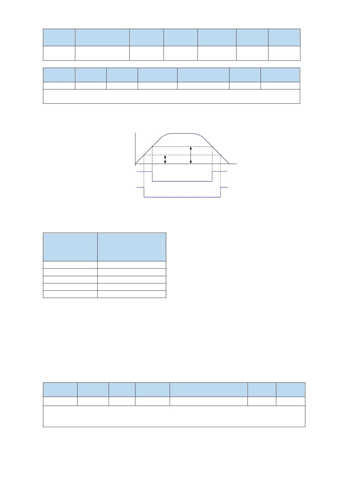
1. Positioning approach signal output conditions
When the pulse deviation value U0-08 of the servo driver is lower than the P5-06 setting value,
the positioning approach signal (/NEAR) is output.
U0-08
Pulse offset
/COIN
signal status
ON
/NEAR
signal status
ON ON
ON
OFF
OFF
P5-00 P5-06
2. Description of approach signal output
(1) The approach signal output width P5-06 changes proportionally due to the change of the electronic
gear ratio. The default setting is 11 command units.
The following table is an example:
Number of
command pulses
required for one
revolution of motor
Near signal output width
P5-06
The near signal output width P5-06 changes
proportionally with the number of command pulses
required for one revolution of the motor.
The output of the positioning completion signal
depends on the positioning completion width. The
smaller the width is, the later the positioning
completion signal output is, but the signal output
does not affect the actual operation state of the
motor.
(2) The approach signal output width can also be set independently, and its change will not affect the
number of command pulses required for one revolution of the motor.
(3) Please set this parameter larger than the positioning completion width.
5.3.1.4 Command pulse prohibition (/INHIBIT)
Position command prohibition, including internal and external position commands. Stop the function of
command pulse input during position control. When the /INHIBIT signal is on, the pulse command is
no longer counted.
Related parameters
Command pulse prohibition
Parameter range n.0000-001A, assigned to other input terminals by parameter P5-32.
If it is necessary to input from SI2, P5-32 can be set to n.0002/0012. Refer to section 3.2.2 for hardware
wiring details.
 Loading...


